Porshe 911 (997). Manual - part 17


  Index      Hummer     Porshe 911 997 series - service repair manual 2004-2008 year


Search            


Content   ..  15  16  17  18   ..


Porshe 911 (997). Manual - part 17


Servo pump

29. Remove hydraulic pump with servo line and supply tank. Undo servo line (a/f 16) -1- , counter on large

hexagon when doing this (a/f 27). Unscrew four Torx screws (3 M8 x 30 at the front -Arrows- , one M8
x 12 at the back), take the servo pump with line and supply tank out of the bracket.

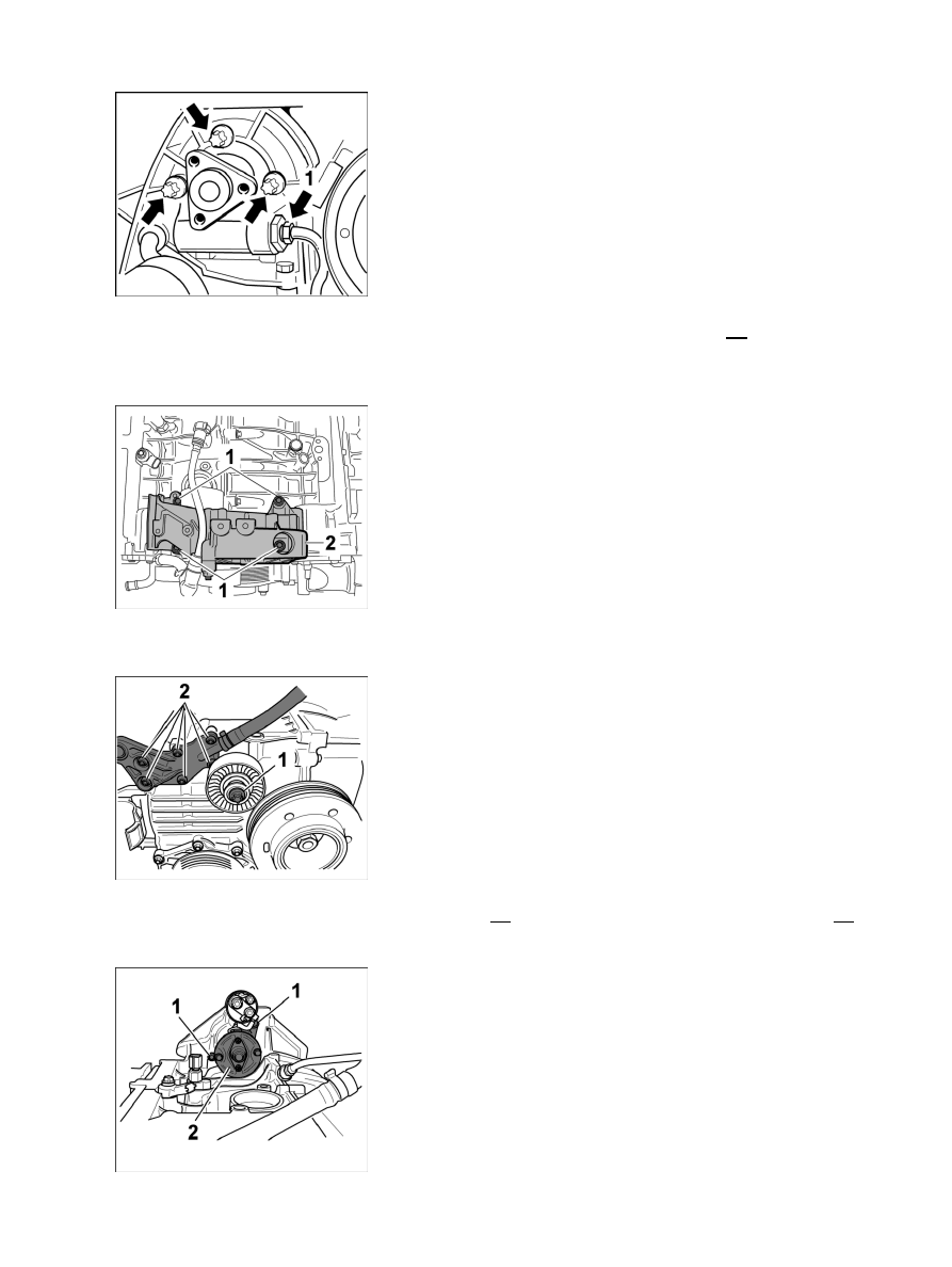
Bracket for servo pump

30. Remove bracket for servo pump. Unscrew 4 M8 x 35 Torx screws, remove bracket.

Deflection roller and closure cap for coolant

31. Remove one M8 x 60 screw for deflection roller -1- and six M6 x 20 Torx screws for closure cap -2- with

bleeder lines for coolant system.

Diagnostic system: reading out fault memory and activating systems

Disassembling engine - up to crankcase

225

Starter

32. Only in manual transmissions: Remove the starter. Unscrew two M10 x 35 Torx screws -1- , take

off starter -2- .

33. Remove oil-level sensor (a/f 19), remove knock sensor, to do this, mark the installation position with a

paint marker, then unscrew one M8 x 35 Torx screw each and take off the sensors.

34. Remove canister for additional volumes of crankcase venting to the cylinder heads 1-3 and 4-6.

Unscrew two M6 x 25 Torx screws each, take off canister. Use new O-rings when installing.

NSD mount

35. Remove the holder for the main muffler on the left and right. Unscrew two M8 x 30 Torx screws each on

the intake side and two M8 x 25 each on the exhaust side and take off mount.

Hydraulic valves for camshaft adjustment \

36. Remove mount and sealing cap for hydraulic valves for camshaft adjustment -2- . Unscrew two M6 x 20

Torx screws each, take off mount and sealing cap.

37. Remove three ignition coils per cylinder side -1- . Unscrew 12 M6 x 25 Torx screws, pull off ignition

coils.

38. Remove six spark plugs. Use only approved tool spark plug socket wrench 14 from Snap-On (in case

ceramic body breaks) → 287020 Removing and installing spark plugs - section on "Removing".

Diagnostic system: reading out fault memory and activating systems

Disassembling engine - up to crankcase

226

Oil strainer hydraulic valve NVS

39. Pull off hydraulic valves for camshaft and valve lift adjustment. To do this, the special tool relay

puller 9235

 can be used. Pull the oil strainer for the camshaft adjustment valve out of the valve

bore -1- with a magnet, replace the oil strainer.

40. Remove the exhaust manifold. Unscrew six M8 x 28 screws each, remove manifold and seal.

41. Remove coolant pipe for heating. Side 1-3: unscrew two M6 x 12 Torx screws, side 4-6: unscrew three

M6 x 12 Torx screws, remove coolant pipe.

42. Remove oil pressure sensor on cylinder head cover 4 - 6 (a/f

19).

43. Remove the mount for the air conditioning compressor. Unscrew two M8 fastening screws, and

remove bracket.

44. Remove hall sender. Unscrew 1 M6 x 16 pan-head screw (hexagon socket a/f 5, micro-encapsulated) and

pull off hall sender, replace screws.

45. Remove knock sensors. Mark installation position (plug connection) with a paint marker, unscrew one

M8 x 35 Torx screw each, pull sensors out of crankcase.

46. Remove speed sender, unscrew one M6 x 16 pan-head screw (hexagon socket a/f 5, micro-encapsulated),

remove sender, replace screw.

Mount for coolant hoses

47. Pull coolant hose assembly out of plastic holder on crankcase. Undo spring band clamps on

water pump and thermostat and take off hoses. Remove mount, to do this, unscrew one M6 x
16 Torx screw (micro-encapsulated), replace screw.

48. Remove all plastic closure caps on the cylinder heads, and replace closure caps.

49. Turn engine on the belt pulley of the crankshaft clockwise to the overlapping TDC of cylinder

bank 1 - 3. To check cylinder 1-3, insert the special tool adjusting gauge 9686 in the camshaft
slots. If the gauge cannot be inserted, the engine must be turned an additional 360°.

Figure

50. Remove oil extraction pump cylinders 1-3. Unscrew four M6 x 20Torx screws (micro-encapsulated),

carefully pull the oil extraction pumps out of the fitting bore. Replace screws.

Diagnostic system: reading out fault memory and activating systems

Disassembling engine - up to crankcase

227

Tandem pump side 4 -6

51. Remove tandem pump on cylinder side 4-6. Unscrew four M6 x 30 fastening screws -1- , pull

vacuum line -2- out of the connection fitting on the pump, take out the pump. Replace O-rings.

Removing camshafts, cylinder bank 1 - 3

Note

The central screws of the camshaft adjustment elements must be undone before removing the cylinder
head cover.

• 

52. The central screws of the camshaft adjuster must be undone before removing the cylinder head covers. To

do this, place special tool retaining tool 9685 on the large hexagon of the central screw and cylinder
head cover and undo the screws.

Figure

53. Remove cylinder head cover → 159119 Removing and installing cylinder head cover - section on

"Removing".

54. Remove all chain tensioners, replace aluminium sealing rings.

55. Remove upper M6 screw (hexagon socket a/f 5) for guide rail cylinder 4-6.

56. Remove camshaft side 1-3 → 150520 Removing and installing camshaft - section on

"Removing" [997430 997431]→ 150520 Removing and installing camshaft - section on
"Removing" [997110 997111 997310 997311 997410 997411 997610 997611]→ 150520 Removing and
installing camshaft - section on "Removing" [997120 997121 997320 997321 997620 997621].

Example of laying aside flat-base tappets

ATTENTION

Interchanged or dirty flat-base tappets.

Damage to engine components

• 

Diagnostic system: reading out fault memory and activating systems

Disassembling engine - up to crankcase

228


Content   ..  15  16  17  18   ..