Snowmobile Ski Doo REV SERIES (2004 year). Manual - part 103


  Index      Snowmobiles / ATV     Snowmobile Ski Doo REV SERIES - service manual 2004 year


Search            


Content   ..  101  102  103  104   ..


Snowmobile Ski Doo REV SERIES (2004 year). Manual - part 103


Section 12 WIRING DIAGRAM

Subsection 01 (WIRING DIAGRAMS)

WIRING DIAGRAMS

Wiring diagrams can be found at the end of this
subsection.

WIRING DIAGRAM LEGEND

WARNING

Ensure all terminals are properly crimped
on the wires and all connector housings are
properly fastened.

A00I04E

XX/XX

1


-


MC

1

2 3 4

D

1. Wire colors
2. Connector housing area
3. Housing code per area
4. Wire connector location in housing

WIRE COLORS

1-


MC

D

A00I04F

XX/XX

XX/XX

The first color of a wire is the main color, second
color is the stripe.

Example: YL / BK is a YELLOW wire with a BLACK
stripe.

COLOR CODE

BE — BEIGE
BK — BLACK
BU — BLUE
BR — BROWN
GN — GREEN
GY — GREY

OR — ORANGE
RD — RED
VI — VIOLET
WH — WHITE
YL — YELLOW

CONNECTOR HOUSING AREA

The first digit of the connector identification num-
ber presents the location of the connector on the
vehicle.

-


MC

D

XX/XX

A00I04G

11

1

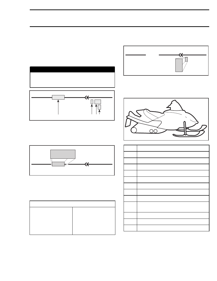
The following illustration shows the snowmobile
with number on it. These numbers will corre-
spond with the locations of the connector on the
vehicle along with a brief description.

7

10

A32H43A

12

11

2

1

8

3

4

9

6

5

AREA

LOCATION

1

Right hand side of engine

2

Engine

3

Near right hand side footrest

4

Near driven pulley

5

Under console

6

Under hood

7

Near fuel tank

8

Under engine

9

Near steering column or on primary air
intake silencer

10

On handlebar

11

Injection oil tank

12

Secondary air intake silencer

HOUSING REFERENCE PER AREA

The next two letters of the connector identifica-
tion number represents a connector reference. If
there are many connectors in the same area this
helps identify which wire is in which connector.

mmr2004-Rev

409

Section 12 WIRING DIAGRAM
Subsection 01 (WIRING DIAGRAMS)


M


C

D

XX/XX

A00I04I

1

MC

WIRE LOCATION IN CONNECTOR
HOUSING

The third portion of the connector identification
number represents the location of the wire in the
connector housing. This could be identified by ei-
ther a number such as 1, 2, 3 or by a letter such as
A, B, C depending on the type of connector used.

XX/XX

A00I04H

D

D

1-


MC

410

mmr2004-Rev

Section 12 WIRING DIAGRAM

Subsection 01 (WIRING DIAGRAMS)

A32E3WS

DEUTSCH

A

C

B

A

C

B

12

11

10

9

8

7

1

2

3

4

5

6

12

11

10

9

8

7

1

2

3

4

5

6

1

2

3

1

2

3

6

5

4

6

5

4

1

2

4

3

4

3

1

2

2

1

1

2

A

B

A

B

A

B

2

1

A

B

C

A

B

C

B

A

A

D

C B

B

C

A

D

A

B

A

B

C

AMP

A

C

B

5

6

7

8

1

1

1 3

2

1 3

2

A

B

KOSTAL

4

3

2

1

1

2

3

4

5

6

6

5

4

3

2

1

4

5

6

7

8

1

2

3

7

8

9

10

11

1

2

3

4

5

6

654 3

21

10

11

12

9 8

13

7

6

5

4

3

2

1

12 11

10 9

8

28

14

1

29

13

41

13

4

3

2

1

7

6

5

2

2

mmr2004-Rev

411

Section 12 WIRING DIAGRAM
Subsection 01 (WIRING DIAGRAMS)

SYMBOLS DESCRIPTION

Beam and tail light

Female terminal

Male terminal

Electronic module

Meter

Electric motor

Low level sensor

Buzzer

Ignition coil

Normally close

switch

Male terminal

on instrument

Engine

ground

Spark plug

Meter movement

Bulb

PilotAnalog sensor

Solenoid valve

Magneto (Delta)

3 position switch

Heating element

Fuse

Normally open

switch

Frame

ground

Frame

Trigger coil

Battery

Diode

Partially illustrated

component

A00E9PS

412

mmr2004-Rev


Content   ..  101  102  103  104   ..