Snowmobile Ski Doo REV SERIES (2004 year). Manual - part 83
Section 09 STEERING/FRONT SUSPENSION
Subsection 01 (STEERING SYSTEM)
A33H05B
2
1
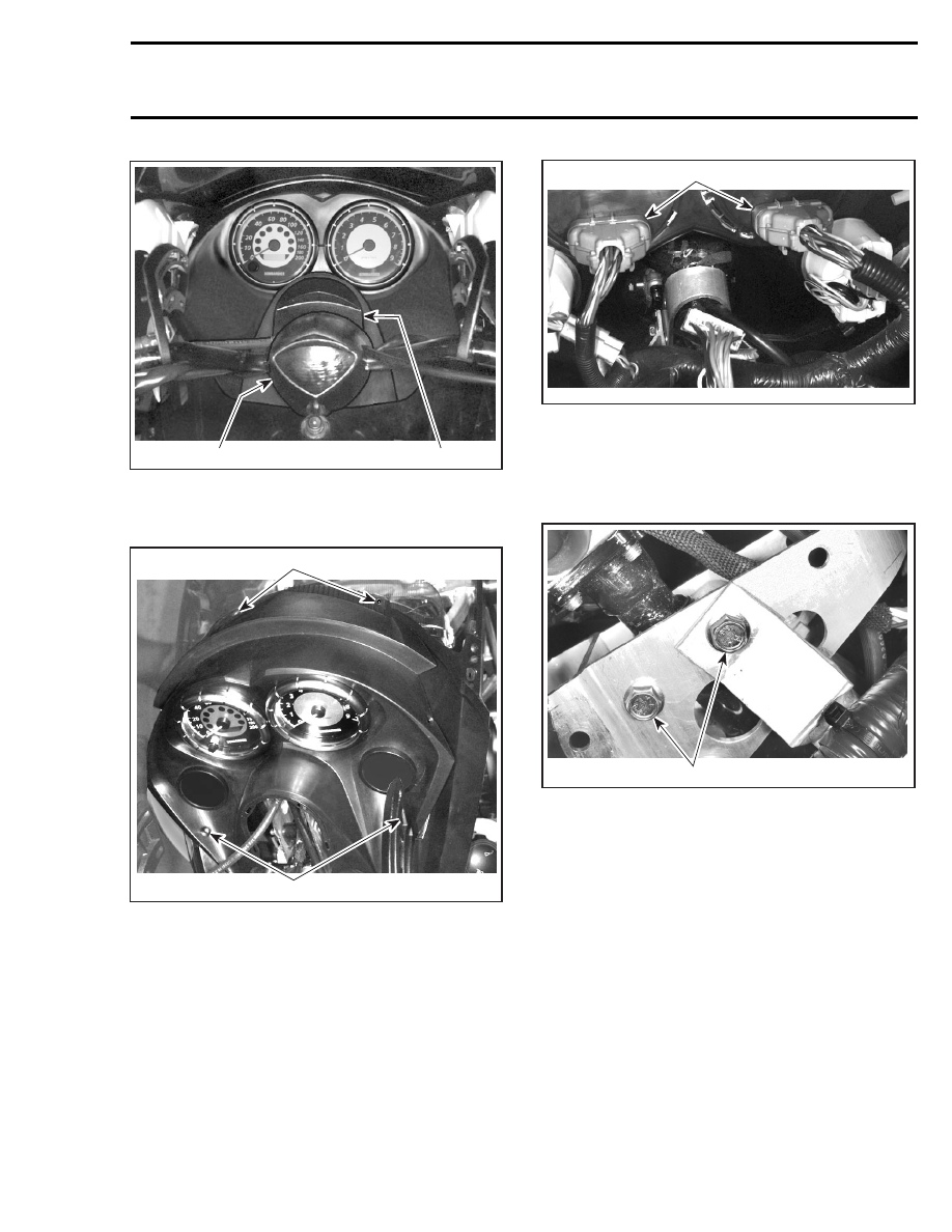
1. Cap
2. Console cap
Unscrew 4 bolts retaining console.
1
A33H06A
1
1. Bolts retaining console
Slightly lift console to gain access to electrical con-
nector housings. Unplug the 2 large connector
housings and then separate 3-wire connector.
1
A33H07A
TYPICAL
1. Large connector housings
Remove console.
Remove 2 bolts no. 5 retaining top of steering col-
umn.
1
A33H08A
STEERING COLUMN IN REARWARD POSITION
1. Two bolts retaining top of steering column
Move steering column to forward position.
mmr2004-Rev
327