Snowmobile Ski Doo REV SERIES (2004 year). Manual - part 61


  Index      Snowmobiles / ATV     Snowmobile Ski Doo REV SERIES - service manual 2004 year


Search            


Content   ..  59  60  61  62   ..


Snowmobile Ski Doo REV SERIES (2004 year). Manual - part 61


Section 06 TRANSMISSION

Subsection 03 (DRIVEN PULLEY)

REMOVAL

Remove guard and drive belt from vehicle.

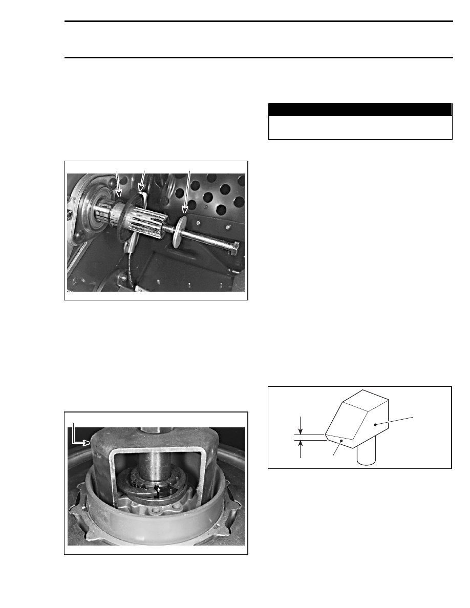
Remove cap screw no. 1 and shouldered washer
no. 3 then pull the driven pulley from the counter-
shaft.

Note shouldered washer position for reinstalla-
tion. Take care not to lose spacer no. 4.

A30D14A

1

2

3

1. Spacer
2. Shoulder on this side
3. Concave side facing driven pulley

Countershaft

Should countershaft no. 5 removal be required, re-
fer to BRAKE then look for COUNTERSHAFT AND
BRAKE DISC REMOVAL.

DISASSEMBLY

Use spring compressor (P/N 529 035 524).

529 035 524

A30D0VA

Remove half keys no. 6 and washer no. 7 to dis-
assemble the cam and the 2 pulley halves.

WARNING

Driven pulley cam is spring loaded, use above
mentioned tool.

CLEANING

Large Bushing and Small Bushing

During break-in period (about 10 hours of use),
teflon from bushing no. 8 and no. 9 moves to cam
or shaft surface. A teflon over teflon running con-
dition occurs, leading to low friction. So it is nor-
mal to see gray teflon deposit on cam or shaft. Do
not remove that deposit, it is not dust.

When a dust deposit has to be removed from the
cam or the shaft, use dry cloth to avoid removing
transferred teflon.

Pulley Half Cleaning

Use pulley flange cleaner (P/N 413 711 809) to
clean pulley halves.

INSPECTION

Slider Shoe

Check cam slider shoes no. 10 for wear. Replace
when inside edge thickness of cam slider shoe
slope base is worn to 1 mm (.039 in) or less.

2

1

A15D0OA

3

1. Measure thickness of slope base here
2. Sliding pulley side
3. Slope base

ASSEMBLY

Cam Slider Shoe

When replacing slider shoes no. 10, always install
a new set (3 shoes) to maintain equal pressure on
the cam.

mmr2004-Rev

233

Section 06 TRANSMISSION
Subsection 03 (DRIVEN PULLEY)

Install slider shoes as per following photo. Red
slider shoes are being used for reverse and black
ones for forward.

A30D0WA

1

1

2

2

2

1

1. BLACK slider shoe
2. RED slider shoe

Screws

Screws no. 12 are machined at their end. With
the adjustment ring steel to position 0 (zero),
screw ends are flush with inner side of fixed
pulley half when tighten.

CAUTION: If any of these screws is not flush
with inner side of sliding pulley, bushings will
worn unequally.

Assemble driven pulley components by reversing
the disassembly procedure.

Cam

Coat cam no. 11 interior with anti-seize lubricant.

INSTALLATION

Countershaft

CAUTION: Always apply anti-seize lubricant
(P/N 293 800 070) on the countershaft before
final pulley installation.

Should installation procedure be required, refer to
BRAKE then look for BRAKE DISC and COUNTER-
SHAFT BEARING ADJUSTMENT.

Reinstall the pulley on the countershaft no. 5 by
reversing the removal procedure.

ADJUSTMENT

Pulley Alignment and Drive Belt Height

Refer to PULLEY DISTANCE AND ALIGNMENT
and DRIVE BELT to perform adjustments.

CAUTION: Drive belt and pulley adjustments
must always be checked whenever pulleys
have been removed, replaced or disassem-
bled.

Cam

Make sure to install proper cam no. 11. Refer to
TECHNICAL DATA.

Cam angle is identified on cam.

A30D0XA

NOTE: For high altitude regions, a service bulletin
will give information about calibration according to
altitude.

234

mmr2004-Rev

Section 06 TRANSMISSION

Subsection 04 (PULLEY DISTANCE AND ALIGNMENT)

PULLEY DISTANCE AND ALIGNMENT

GENERAL

Both pulley distance and pulley alignment must be
checked out to ensure the highest efficiency of
the transmission system. Furthermore, optimum
drive belt operation and minimal wear will be ob-
tained only with proper pulley alignment.

CAUTION: Before checking pulley adjustment,
the rear suspension must be mounted on the
vehicle and track tension/alignment must be
done. Always check pulley adjustment after
suspension is adjusted.

WARNING

Failure to correctly perform pulley alignment
may cause the vehicle to creep forward at
idle.

All Pulley Alignment Specifications Refer to:

X = Distance between straight bar and drive pulley
fixed half edge, measured between pulleys.

Y = Distance between straight bar and drive pulley
fixed half edge, measured at the end of straight
bar.

Z = Distance between outside diameter of pulleys
(not adjustable on the REV Series models).

GENERAL PROCEDURE

Remove guard, drive belt and air silencer.

Loosen lock nut.

1

A33D0FA

1. Lock nut

Untighten torque rod using a long hexagonal key.

1

A33D0GA

2

TYPICAL

1. Torque rod
2. Hexagonal key

By using driven pulley opening tool (P/N 529 017
200) push the sliding half to open the driven pulley.

529 017 200

A33D0HA

DRIVEN PULLEY OPENING TOOL

Insert a straight bar 9.5 mm (.373 in) square, 48 cm
(19 in) long or the proper alignment bar into the
opened driven pulley.

mmr2004-Rev

235

Section 06 TRANSMISSION
Subsection 04 (PULLEY DISTANCE AND ALIGNMENT)

Measuring Procedure

Using Straight Bar

Always measure distances X and Y from the far-
ther straight bar side (including its thickness to the
fixed half edge).

A00D0WA

1

2

Z

X

Y

TYPICAL
1. Straight bar
2. Front of vehicle

The distance Y

must

exceed distance X to com-

pensate for the twist due to the engine torque.

Drive Belt Deflection

NOTE: When pulley distance and alignment are
adjusted to specifications, refer to DRIVE BELT to
adjust drive belt deflection.

CAUTION: This section deals mainly with ad-
justment procedures. For complete assembly
requirements, refer to the proper ENGINE or
TRANSMISSION installation section.

PULLEY ALIGNMENT AND DISTANCE SPECIFICATIONS CHART

PULLEY

DISTANCE

OFFSET

Z

X

Y-X

MODEL

± 0.50 mm (.020 in)

ALIGNMENT

BAR

P/N

ALL REV SERIES MODELS WITH
FORMULA VSA OR FORMULA VSA
RER

19.0 (0.748)

37.0 (1.456)

1.5 (0.060)

ALL REV SERIES MODELS WITH HPV
VSA

20.0 (0.787)

37.0 (1.456)

1.5 (0.060)

529 035 831

236

mmr2004-Rev


Content   ..  59  60  61  62   ..