Snowmobile Ski Doo REV SERIES (2004 year). Manual - part 42
Section 04 ENGINE
Subsection 07 (CARBURETOR AND THROTTLE CABLE)
A06E2OA
1
2
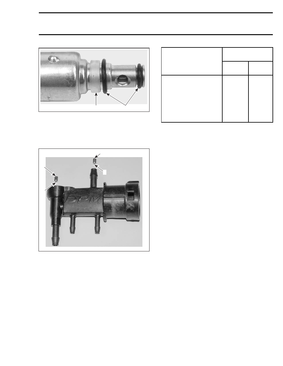
1. Plastic seal
2. O-rings
Jet
When installing jet no. 18 in DPM, ensure to posi-
tion the taper end as shown.
1
A32C6WA
3
2
3
1. Vent jet
2. Lean jet
3. Taper end here
Pay also attention not to mix jets. Refer to the
following table for the proper inner diameter size.
Refer to the illustration above for the jet location.
INSIDE DIAMETER
mm (in)
MODEL
VENT JET
LEAN
JET
GSX 800 R Limited
MX Z 600 R Renegade
MX Z 800 R
Adrenaline/Renegade/
Renegade X/X
Summit 600 R Adrenaline/X
Summit 800 R Adrenaline/
HM/HM X/HM Xtrem/X
1.2 (.047)
2.0 (.079)
Cap
Prior to installing cap no. 19, ensure O-ring is in
good condition. To install cap, firmly push until
tabs click and lock on both sides in DPM.
DPM MANIFOLD TESTING
Visual Inspection
With DPM manifold removed from vehicle and all
hoses disconnected from DPM manifold, inspect
for any broken fittings or missing dust caps. If any
part is broken, replace DPM manifold and do not
proceed with leak test procedure. If any part is
missing, order necessary part as listed in parts cat-
alog, replace, then perform leak test procedure.
If there is no apparent breakage or missing part
on DPM manifold, perform the following leak test
procedure.
Leak Testing
Required Items
The following items will be required:
– Water column with at least 350 mm (13-3/4 in)
in height.
– Engine leak test kit (P/N 861 749 100).
– 4.8 mm (3/16 in) T-fitting.
– 6 mm (15/64 in) T-fitting.
– 3.5 mm (9/64 in) ID x 100 mm (4 in) hose.
– 6 mm (15/64 in) ID x 300 mm (12 in) hose.
DPM Manifold Preparation
Connect hoses as shown.
mmr2004-Rev
153