Snowmobile Ski Doo REV SERIES (2004 year). Manual - part 40
Section 04 ENGINE
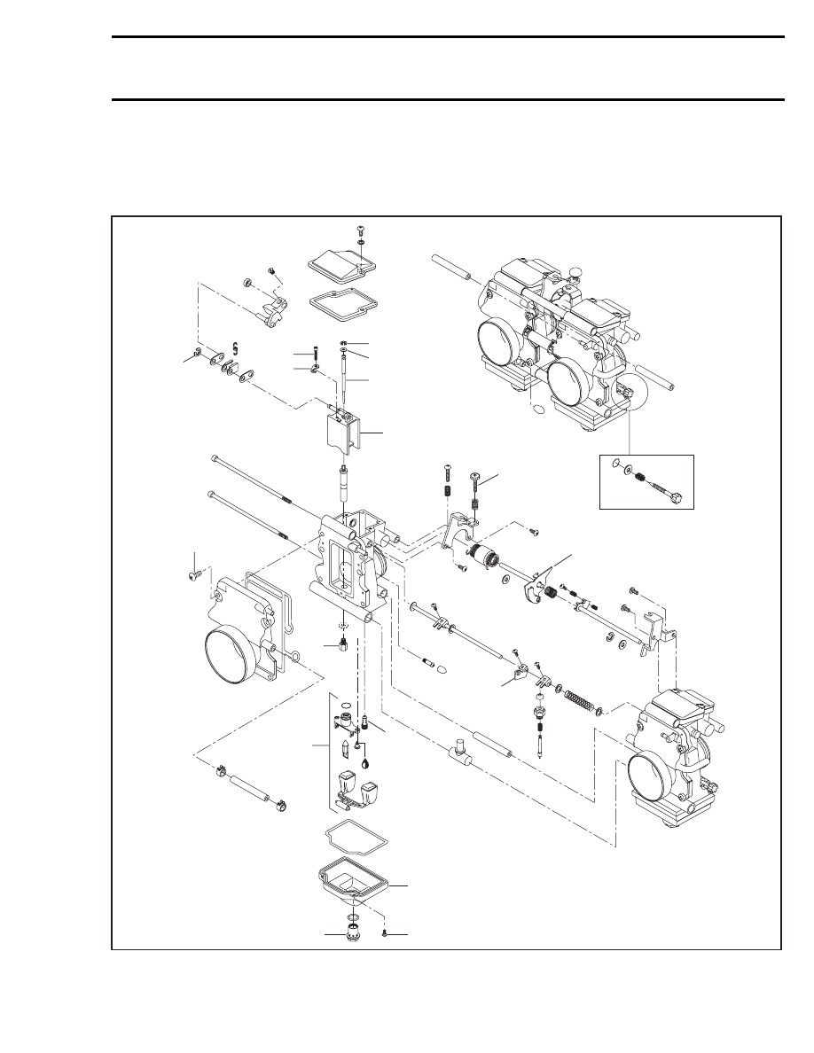
Subsection 07 (CARBURETOR AND THROTTLE CABLE)
CARBURETOR AND THROTTLE CABLE
CARBURETOR TM TYPE
A32C6ZT
12
PTO
MAG
11
10
8
9
14
13
15
4
5
7
1
6
3
2
16
17
Loctite 243
mmr2004-Rev
145