Snowmobile Ski Doo REV SERIES (2004 year). Manual - part 34


  Index      Snowmobiles / ATV     Snowmobile Ski Doo REV SERIES - service manual 2004 year


Search            


Content   ..  32  33  34  35   ..


Snowmobile Ski Doo REV SERIES (2004 year). Manual - part 34


Section 04 ENGINE
Subsection 02 (ENGINE LEAK TEST AND DIMENSION MEASUREMENT)

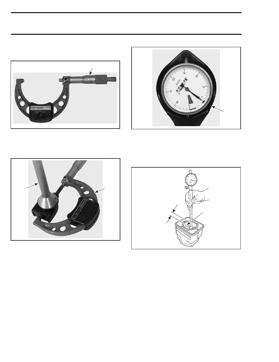
Adjust and lock a micrometer to the specified
value on the piston dome.

F00B08A

1

1. Micrometer set to the piston dimension

With the micrometer set to the piston dimension,
adjust a cylinder bore gauge to the micrometer
dimension and set the indicator to 0.

F00B09A

1

2

1. Use the micrometer to set the cylinder bore gauge
2. Dial bore gauge

F00B0AA

1

1. Indicator set to 0 (zero)

IMPORTANT: Always remove cylinders from
crankcase before measuring.

Position the dial bore gauge at 16 mm (5/8 in) be-
low cylinder top edge.

F01D0KA

1

A

1. Measuring perpendicularly (90°) to piston pin axis

A. 16 mm (5/8 in)

Read the measurement on the cylinder bore
gauge. The result is the exact piston/cylinder
wall clearance. If clearance exceeds specified
tolerance, replace cylinder or rebore and install
oversize piston depending on engine type. Refer
to TECHNICAL DATA.

NOTE: Make sure the cylinder bore gauge indica-
tor is set exactly at the same position as with the
micrometer, otherwise the reading will be false.

IMPORTANT: The total piston/cylinder clearance
(actual cylinder diameter minus actual piston skirt
diameter) should be within 0.30 mm (.012 in).

118

mmr2004-Rev

Section 04 ENGINE

Subsection 02 (ENGINE LEAK TEST AND DIMENSION MEASUREMENT)

RING/PISTON GROOVE
CLEARANCE

Using a feeler gauge check clearance between
rectangular ring and groove. Replace piston if
clearance exceeds specified tolerance. Refer to
TECHNICAL DATA.

A01C0PA

RING END GAP

Position ring half-way between transfer ports and
intake port.

NOTE: In order to correctly position the ring in the
cylinder, use piston as a pusher.

Using a feeler gauge, check ring end gap. Replace
ring if gap exceeds specified tolerance. Refer to
TECHNICAL DATA.

A01C0QA

2

1

1. Transfer port
2. Intake port

CRANKSHAFT DEFLECTION

Crankshaft deflection is measured with a dial indi-
cator.

Measuring (in crankcase)

First,

check

deflection

with

crankshaft

in

crankcase. If deflection exceeds the specified tol-
erance, recheck deflection using V-shaped blocks
to determine the defective part(s). See below.

Measuring (on bench)

Once engine is disassembled, check crankshaft
deflection on V-shaped blocks.

If deflection

exceeds the specified tolerance, it can be worn
bearings or a bent crankshaft. Remove crankshaft
bearings and check deflection again on V-shaped
blocks to determine the defective part(s). See
measurement A in following illustration.

A01C0RD

1

A

TYPICAL
1. Measure at mid point between the key and the first thread

A. 3 mm (1/8 in)

Crankshaft Deflection on PTO Side

ENGINE

TYPE

MAXIMUM ON PTO SIDE

mm (in)

All

0.06 (.0024)

Crankshaft Deflection on MAG Side

ENGINE

TYPE

MAXIMUM ON MAG SIDE

mm (in)

593, 593

HO/SDI,

793 HO

0.05 (.002)

mmr2004-Rev

119

Section 04 ENGINE
Subsection 02 (ENGINE LEAK TEST AND DIMENSION MEASUREMENT)

Crankshaft Deflection in Center of Crankshaft

ENGINE

TYPE

MAXIMUM IN CENTER OF

CRANKSHAFT mm (in)

All

0.08 (.0031)

NOTE: Crankshaft deflection cannot be correctly
measured between centers of a lathe.

If the deflection exceeds the specified tolerance,
crankshaft should be repaired or replaced.

CONNECTING ROD BIG END
AXIAL PLAY

ENGINE

TYPE

NEW PARTS

MIN. — MAX.

WEAR

LIMIT

593

0.39 - 0.74 mm

(.015 - .029 in)

1.20 mm

(.047 in)

593 HO/SDI,
693, 793 HO

0.31 - 0.67 mm

(.012 - .026 in)

1.20 mm

(.047 in)

Using a feeler gauge, measure distance between
thrust washer and crankshaft counterweight. If
the distance exceeds specified tolerance, repair or
replace the crankshaft.

A01C0SA

TYPICAL

CRANKSHAFT END-PLAY

End-play is not adjustable but it should be be-
tween 0.10 - 0.30 mm (.004 - .012 in).

CHECKING CRANKSHAFT
ALIGNMENT

Install a degree wheel (P/N 529 035 607) on crank-
shaft end.

Remove both spark plugs.

Install a TDC gauge (P/N 414 104 700) in spark plug
hole on MAG side.

Bring MAG piston at top dead center.

Rotate degree wheel (not crankshaft) so that 360°
mark aligns with center of crankcase. Scribe a
mark on crankcase.

Remove TDC gauge and install it on center cylin-
der.

Bring PTO piston to top dead center. Degree
wheel must rotate with crankshaft.

0

90

80

70

60

50

40

30

20

10

180

0

A06C1TA

TYPICAL

Interval between cylinders must be 180° ± 0.5.

Any other reading indicates a misaligned (twisted)
crankshaft.

120

mmr2004-Rev

Section 04 ENGINE

Subsection 03 (MAGNETO SYSTEM)

MAGNETO SYSTEM

A33E0MT

To regulator

Silastic 732

Loctite 243

22 N•m

(195 lbf•in)

Loctite 243

125 N•m

(92 lbf•ft)

1

Air sensor

DPM

To main harness

To main harness

2

Loctite 648

7

3

4

5

RER

models

Sikaflex 255

6

mmr2004-Rev

121


Content   ..  32  33  34  35   ..