Snowmobile Ski Doo REV SERIES (2004 year). Manual - part 31


  Index      Snowmobiles / ATV     Snowmobile Ski Doo REV SERIES - service manual 2004 year


Search            


Content   ..  29  30  31  32   ..


Snowmobile Ski Doo REV SERIES (2004 year). Manual - part 31


Section 04 ENGINE

Subsection 01 (593, 593 HO, 593 HO SDI AND 793 HO ENGINE TYPES)

A32CAUA

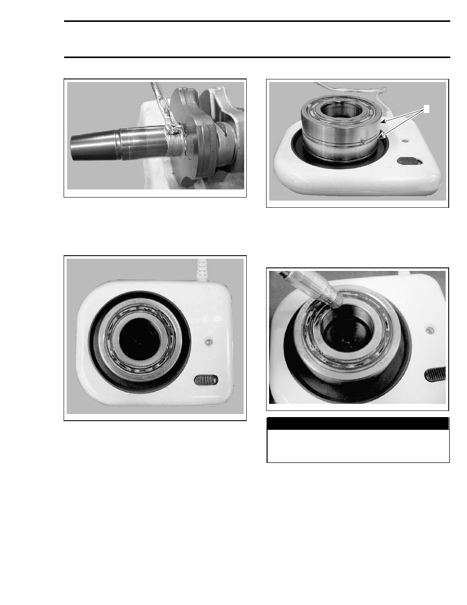
Heat up the bearing(s) using bearing heater
(P/N 529 035 969). This will expand bearings
and ease installation. If required, put a suitable
plate or shim to avoid the direct contact between
integrated seal with the heating surface.

A32CB7A

CAUTION: Bearing(s) should not be heated to
more than 80°C (176°F). Do not heat bearing(s)
on direct flame, or with a heat gun or in an
oil bath. Inappropriate bearing(s) heating may
result in inner seals or cage failure.

Turn bearing several times to obtain an even heat-
ing process.

NOTE: Normally it takes approximately 10 min-
utes to heat up a bearing so in the event of replac-
ing bearing, it’s recommended to start the bearing
heating process prior to removal operation. Two
bearings can be heated at the same time on one
bearing heater.

A32CB8A

1

1. Bearings

Probe the inner race of the bearing with the tem-
perature indicator stick (P/N 529 035 970). Stick
will liquefy when the bearing reach the proper
temperature

A32CB9A

WARNING

Do not touch heated bearing with bare hands.
Always wear heat resisting gloves before
handling the heated bearing(s).

Slide in the inner PTO bearing with the integrated
seal facing crankshaft. Push bearing to end posi-
tion.

mmr2004-Rev

105

Section 04 ENGINE
Subsection 01 (593, 593 HO, 593 HO SDI AND 793 HO ENGINE TYPES)

A32CAVA

NOTE: Heated bearings will slide onto the crank-
shaft. If required, push with a steel tube on the
inner ring of the bearing. Pay special attention
to correct positioning of the drive pins and/or
retaining discs.

Install retaining discs.

Install support plate (P/N 529 035 976) with appro-
priate distance gauge; refer to following table.

DISTANCE GAUGE

P/N

APPLICATION

529 035 966

593 engine

529 035 967

593 HO

529 035 968

593 SDI and 793 HO

A32CBCA

2

1

1. Support plate
2. Distance gauge

Install bearing locator tool.

A32CAWA

Slide in the heated outer PTO bearing onto the
crankshaft until it contacts the distance gauge.

Slide-in the first MAG bearing with the integrated
seal facing crankshaft. Push bearing to the bot-
tom with pusher , using a rubber hammer.

106

mmr2004-Rev

Section 04 ENGINE

Subsection 01 (593, 593 HO, 593 HO SDI AND 793 HO ENGINE TYPES)

A32CC4B

Slide-in the second bearing until it contacts the
first one.

A32CC5B

NOTE: To prevent seal pop-out, it is recom-
mended to use PTO seal

CAUTION: Use only the recommended Isoflex
grease.

Make

sure

not

to

push

Isoflex

grease between outside bearing race and
half crankcase.

NOTE: The 50 g tube corresponds to 50 cc of
grease.

Put 50 to 55 mL of grease in a syringe.

CAUTION: Do not exceed the recommended
amount of grease

Fill inner side of PTO side bearing with Isoflex
grease (about 10 mL).

A33C15A

PTO SIDE BEARING FILLED WITH ISOFLEX GREASE

With the syringe, fill the outer ball bearing and in-
ner side of outer seal with 40 to 45 mL of Isoflex
grease.

A33C16A

BALLS COATED WITH A SEAM OF GREASE

mmr2004-Rev

107

Section 04 ENGINE
Subsection 01 (593, 593 HO, 593 HO SDI AND 793 HO ENGINE TYPES)

A33C17A

TYPICAL — FILL WITH GREASE AND SET IN PLACE

Apply 6 mL of grease to MAG side outer bearing.

NOTE: If replaced with new bearing, do not apply
grease as new bearings come with grease already
applied.

At crankshaft installation, position drive pins as il-
lustrated.

1

A32C1CA

TYPICAL
1. Position pins

Pour 50 mL (2 U.S. oz) of injection oil in the pan
under central gear to lubricate pump gearing as
per photo.

1

A32C0DA

1. Oil bath

Crankcase Assembly

IMPORTANT: The total assembly sequence, in-
cluding sealing compound spreading, screwing
and torquing of bolts according to the proper
sequence, must be performed within 10 minutes.
Do not wait between each bolt torquing. All bolts
must be torqued in a row.

Before screwing both parts of crankcase, seal it
with sealing compound (P/N 420 297 906). Make
sure surfaces are clean and degreased before ap-
plying sealing compound.

Spread a seam of 1.2 mm (1/16 in) maximum in
diameter on surface of lower crankcase half.

A32C0EA

As far as possible, sealing compound must be
applied in one run to avoid any risks of leakage
through the crankcase.

108

mmr2004-Rev


Content   ..  29  30  31  32   ..