Snowmobile Arctic Cat (2008 year). Manual - part 145
7-140
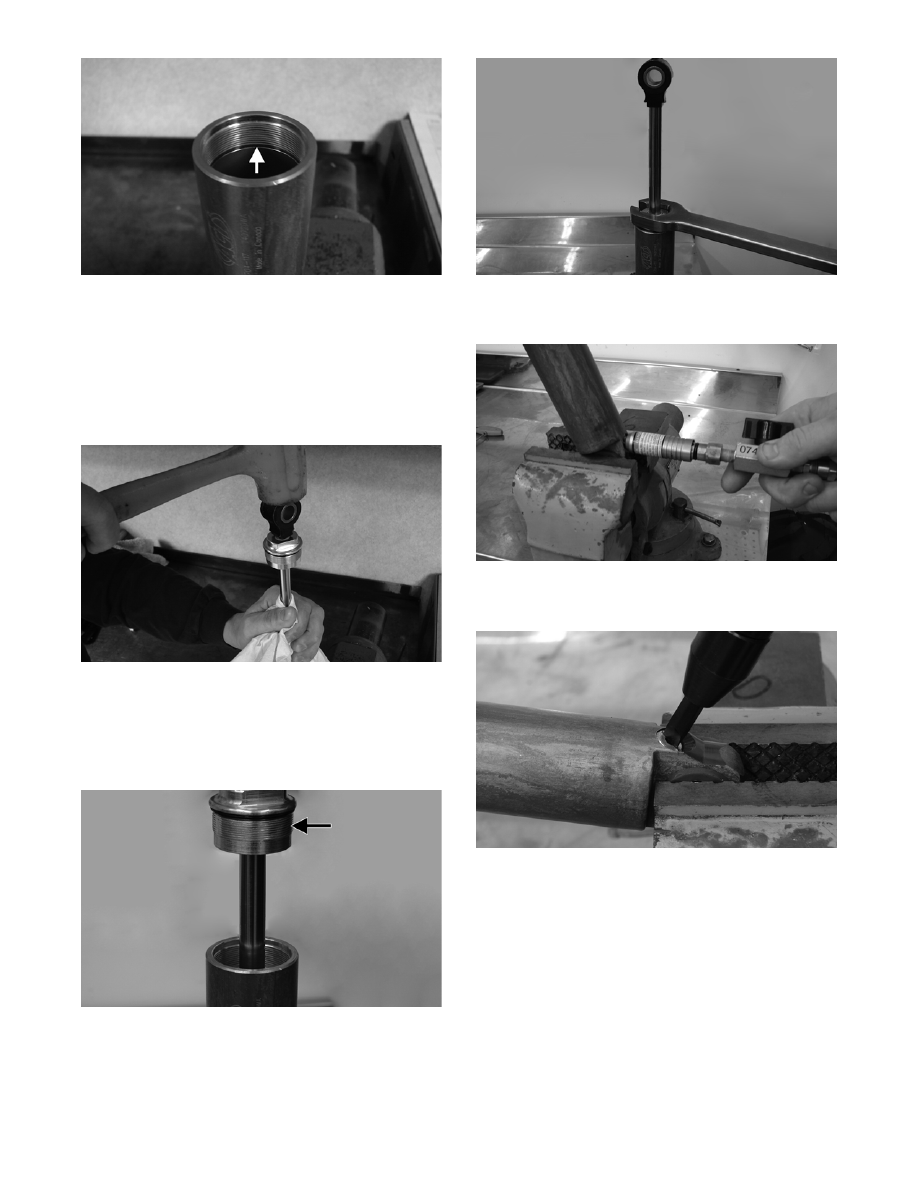
FS257A
6. With the bearing assembly positioned at the top of
the shock rod, install the shock rod/piston assem-
bly into body; then with the top of the shock body
and rod covered with a shop towel, tap the top of
the rod eyelet with a soft hammer.
NOTE: Ensure that the piston/valve stack is
completely submerged in shock oil.
FS258
NOTE: Tapping the eyelet will allow air to
escape from the valve stack/piston assembly.
7. While holding up on the eyelet, thread the bearing
assembly into the body.
FS259A
8. Using a 1-in. wrench, tighten the bearing assem-
bly.
FS252
9. Pressurize the shock with nitrogen to 200 psi (see
Pressurizing Rebuildable Shocks sub-section).
FS251
10. Install the valve screw (with O-ring) into the pres-
sure valve assembly.
FS253
11. Test operation of the shock.
NOTE: Shock should feel soft on compression;
constant on rebound.