Snowmobile Arctic Cat (2008 year). Manual - part 144


  Index      Snowmobiles / ATV     Snowmobile Arctic Cat - service manual 2008 year


Search            


Content   ..  142  143  144  145   ..


Snowmobile Arctic Cat (2008 year). Manual - part 144


7-136

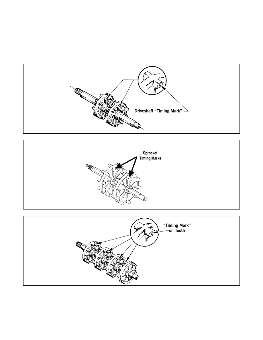
Drive Sprocket Locations

The following illustrations will provide all necessary

information to relocate sprockets on the driveshaft.

When information is required to assemble the drive-

shaft, refer to the parts manual for model being worked

on; then refer to the following illustrations using the

part number listed in the parts manual as a reference.

When pressing new sprockets on the driveshaft,

remember to align the sprocket alignment marks or the

sprockets won’t be timed correctly. See following

illustrations.

0728-351

737-870A

0727-829

7-137

7

727-829B

740-043A

740-044A

7-138

Servicing ACT Shock

REMOVING/CLEANING

1. Remove the shock from the snowmobile.

2. Wash the shock body in parts-cleaning solvent;

then dry with compressed air to remove sand and

dirt.

DISASSEMBLING

1. Remove the screw from the pressure valve assem-

bly on the bottom of the shock. Discharge all the

pressure from the shock using the Inflation Nee-

dle. Open the valve in filler handle until all pres-

sure is released.

FS250

FS251

2. Using a 1-in. wrench, loosen the bearing assembly

and remove the shock rod and valve assembly

from the shock body.

FS252

FS055

3. Pour the oil from the shock body into a suitable

container.

4. Remove the pressure valve assembly. Account for

the O-ring.

FS253

5. Using Floating Piston Removal Tool, remove the

floating piston.

! WARNING

Before any service is performed on the gas shock
absorber, first discharge all pressure from the shock
remote reservoir. Remove the valve screw from the
pressure valve and insert the Inflation Needle. Open
valve until all pressure is released. Failure to do this
may cause personal injury.

! WARNING

When using compressed air to dry components,
always wear safety glasses.

7-139

7

FS254

6. Items to inspect:

A. Shock shaft for straightness, nicks, or burrs.

B. Shaft bearing end cap — clean, inspect, or

replace.

C. Inside of shock body for scratches, burrs, or

excessive wear.

D. Piston strap for cuts, chipped or nicked edges,

or excessive wear.

E. O-rings for nicks, cuts, or cracks.

F. Valves for kinks or waves.

G. Rubber damper (ski shocks only) for chipping,

cracking, or being missing.

7. Items to replace:

A. Floating piston O-ring.

B. Shock shaft bearing cap if any signs of oil leaks

or damage.

C. Any part worn or damaged.

„NOTE: For shaft eyelet replacement, see Shaft
Eyelet sub-section.

ASSEMBLING

1. Set Floating Piston Installation/Location Tool to

5.80 in.

FS255

2. Lubricate the O-ring and Teflon strap on floating

piston; then press the floating piston into shock

until flush with the top of the body.

FS063

FS256

3. Install floating piston tool onto floating piston;

then press floating piston into shock body 5.80 in.

4. Install the pressure valve assembly and tighten to

15-18 ft-lb.

FS253

5. Fill shock body with lightweight synthetic Shock

Oil to bottom of threads.


Content   ..  142  143  144  145   ..