Snowmobile Arctic Cat (2008 year). Manual - part 130


  Index      Snowmobiles / ATV     Snowmobile Arctic Cat - service manual 2008 year


Search            


Content   ..  128  129  130  131   ..


Snowmobile Arctic Cat (2008 year). Manual - part 130


7-80

CM237

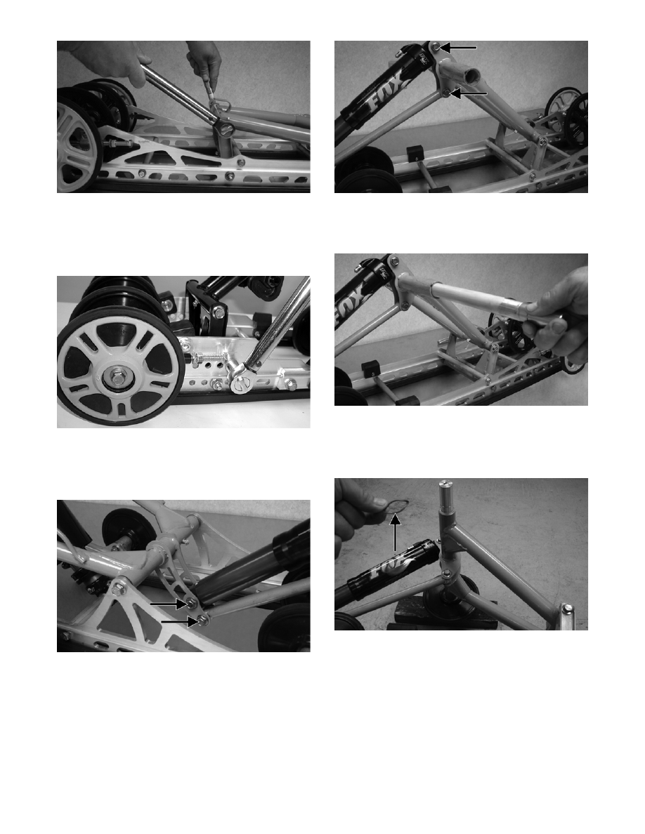
„NOTE: If the rear arm limiter and rail support
were loosened (after step 4 of disassembling),
coat the threads of the cap screw with blue Loctite
#243 and tighten to 30 ft-lb.

MS158

3. With the sleeves installed, place the shock

absorber and shock link between the pivot arm

bracket. Secure with the cap screws and lock nuts.

Tighten securely.

CM233A

„NOTE: Do not over-tighten the shock absorber
cap screw as the shock eyelet must be free to
pivot.

4. With the sleeves installed, position the shock link

in the appropriate holes of the idler arm brackets

and shock absorber; then insert the cap screw

through the eyelets. Secure with the cap screws

and lock nuts. Tighten securely.

CM234A

5. Install the inner carriage axle to the idler arm; then

install a wave washer and idler wheel. Secure with

the snap ring.

CM232

6. Turn the slide rail onto the side the idler wheel was

installed in (from step 5); then with a block of

wood placed under the inner carriage axle/idler

arm, install a wave washer.

CM238A

7. Install the remaining idler wheel along with the

snap ring onto the axle; then using a suitable driv-

ing tool, carefully drive the snap ring into the idler

wheel until it is properly seated in the groove of

the axle.

7-81

7

CM239

8. Grease the idler arm and rear arm grease fittings

with a low-temperature grease.

Front Arm Assembly

„NOTE: The skid frame must be removed for this
procedure (see Removing Skid Frame in this sub-
section), and the rear springs must be removed
from the adjusting cams.

REMOVING

1. Remove the cap screws and lock nuts securing the

rear arm shock absorber and shock link to the front

arm pivot and account for the sleeves.

CM233A

2. Remove the cap screws and lock nuts securing the

limiter straps to the front arm. Account for flat

washers.

CM240A

3. Remove the cap screw and lock nut securing the

shock absorber to the front arm. Pull the shock

eyelet free of the bracket. Account for a serrated

axle.

CM241

4. Remove the cap screws and lock nuts securing the

front arm to the slide rails.

CM242A

5. Remove the front arm and account for the two

front arm spacers.

MS164

6. To access the front shock axle cap screws, remove

the cap screw securing the front outer idler wheel

to the idler wheel mounting block. Account for

lock nut, cap screw, and flat washers.

7-82

CM243A

7. Remove the cap screw, washer, and lock nut from

the front shock axle; then from one side, tap the

assembly rearward far enough for the axle assem-

bly to clear the slide rails. Account for an axle, two

spacers, two shim washers, and rubber bushing.

„NOTE: It may be necessary to loosen the front
rail support cap screws enough to gain clearance
to remove the front shock axle.

CM244

CM245

INSPECTING

„NOTE: Whenever a part is worn excessively,
cracked, or damaged in any way, replacement is
necessary.

1. Inspect all front arm weldments for cracks or

unusual bends; then inspect the front arm mount-

ing brackets for cracks and for elongated holes.

2. Closely inspect all tubing for cracks or unusual

bends.

3. Inspect the bearings, bushings, and front arm spac-

ers for wear or damage.

4. Inspect the shock absorber for any signs of oil

leakage especially at the point where the shock

shaft enters the shock body.

5. Inspect the shock absorber for body damage and

eyelet weld damage (at each end) for any cracks,

signs of separation, or for unthreading.

INSTALLING

1. With the rubber bushing in the eyelet, install the

axle into the lower shock eyelet bushing assembly;

then install the two shim washers and the two

spacers.

„NOTE: To aid in installing the axle, apply a light
coat of lubricant to the inside of the bushing.

CM246A

2. Place the front arm shock axle assembly into posi-

tion on the skid frame making sure the spacers and

washers are properly positioned. Secure with the

cap screw, washer, and a new lock nut. Tighten to

40 ft-lb.

„NOTE: If the front rail support cap screws were
loosened (after step 6 of removing), treat the
threads with blue Loctite #243 and tighten to 30 ft-
lb.

3. Secure the front outer idler wheel to the idler

wheel mounting block with cap screws, flat wash-

ers, and lock nuts. Tighten to 34 ft-lb.

7-83

7

CM243A

4. Position the front arm with aluminum axle to the

mounting location in the slide rail. Secure with cap

screws (coated with blue Loctite #243). Tighten to

50 ft-lb.

CM248

5. With the serrated axle installed, secure the shock

absorber in the appropriate mounting hole of the

front arm. Secure with a cap screw and lock nut.

Tighten securely.

CM241

„NOTE: Do not over-tighten the shock absorber
cap screw as the shock eyelet must be free to
pivot.

6. Secure the rear arm shock absorber and shock link

to the pivot arm bracket with cap screws and lock

nuts. Tighten securely.

CM233A

7. Secure the limiter straps with cap screws, washers,

and lock nuts. Tighten to 5.5 ft-lb.

CM240A

Slide Rails

„NOTE: The skid frame must be removed for this
procedure (see Removing Skid Frame in this sub-
section).

REMOVING

„NOTE: When it is necessary to replace one or
both slide rails, it is recommended that one slide
rail be removed at a time. The remaining slide rail
will then hold the crossbraces, axles, and brackets
in their correct assembly order. Always mark the
mounting hole locations during disassembly to
speed up the assembly process and to prevent any
damage. This method is much quicker than to
completely disassemble the entire skid frame. To
replace either rail, use the following procedure.

1. Remove the end cap from the slide rail. Account

for a cap screw, lock nut, and two flat washers.


Content   ..  128  129  130  131   ..