Snowmobile Arctic Cat (2008 year). Manual - part 129


  Index      Snowmobiles / ATV     Snowmobile Arctic Cat - service manual 2008 year


Search            


Content   ..  127  128  129  130   ..


Snowmobile Arctic Cat (2008 year). Manual - part 129


7-76

CM230

REMOVING SLIDE RAIL INNER 
WHEELS

„NOTE: The skid frame does not have to be
removed for this procedure.

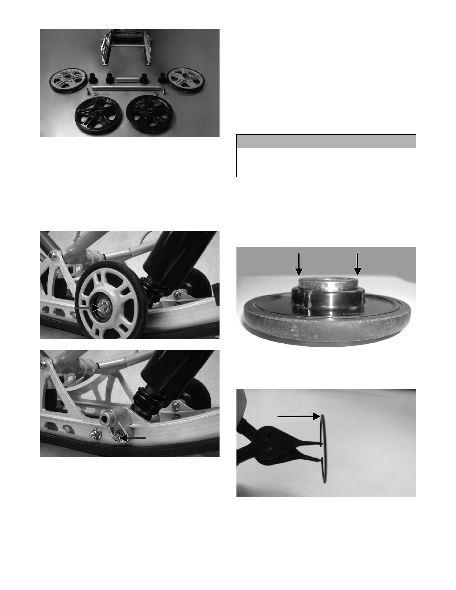
1. Remove the cap screw and lock nut securing the

idler wheel and the idler wheel mounting block.

CM226A

CM227A

2. Account for the flat washer.

CLEANING AND INSPECTING

„NOTE: Whenever a part is worn excessively,
cracked, or damaged in any way, replacement is
necessary.

1. Clean the bearings with a clean cloth.

2. Inspect all idler wheel inserts (inner and outer) for

any cracks.

3. Inspect the idler wheels for cracks, damage, or

poor bonding of the outer rubber portion.

4. Inspect the shaft for wear and damaged threads.

5. Inspect all idler wheel bearings. Turn each bearing

(by hand) and if any roughness or binding is noted,

replace the bearing.

6. If a bearing must be replaced, use this procedure.

A. Remove the bearing snap ring.

B. Using a suitable press or driving tool, remove

the bearing from the inside of the wheel.

C. Press the new bearing (on its outer race) into

the idler wheel.

MS006A

D. Install the snap ring making sure the “sharp

side” is directed away from the bearing.

MS007A

INSTALLING SLIDE RAIL IDLER 
WHEELS

1. Secure the mounting block on the slide rail with a

cap screw and lock nut. Tighten to 34 ft-lb.

! CAUTION

Do not remove the bearing unless it is absolutely
necessary. The bearing will be damaged during
removal.

7-77

7

„NOTE: For proper alignment, it is advisable to
install an idler wheel cap screw into the top mount-
ing block hole prior to tightening.

CM228A

2. Place the idler wheel to the mounting block; then

secure the idler wheel assembly with a cap screw,

flat washer, and a lock nut. Tighten to 34 ft-lb.

CM229

ASSEMBLING REAR AXLE

742-863A

1. In order from the right-hand side, slide the axle

through the slide rail axle slot; then place a bush-

ing (A), inner idler wheel (B), rear idler wheel

spacer (C), inner idler wheel (D), and bushing (E)

on the axle. Slide the axle through the opposite

slide rail axle slot.

2. Place the plastic adjuster bushings on the axle (on

the outside of each axle slot); then install the outer

idler wheels on the axle and secure with two cap

screws (coated with blue Loctite #243) and large

flat washers. Tighten cap screws only until snug.

CM225

CM224A

„NOTE: Make sure the hole in the bushing is
directed to the adjusted bolt.

CM261A

„NOTE: It is advisable to tighten the rear idler
wheel axle only until snug until the skid frame has
been installed and track tension has been
adjusted; then the axle assembly must be tight-
ened to 50 ft-lb.

3. Install the skid frame (see Installing Skid Frame in

this sub-section).

4. Adjust track alignment (see Track Alignment in

this sub-section).

7-78

5. Adjust track tension deflection (see Track Tension

in this sub-section).

Rear Arm Assembly

„NOTE: The skid frame must be removed for this
procedure (see Removing Skid Frame in this sub-
section).

DISASSEMBLING

1. Remove the snap ring securing the rear arm idler

wheels to the inner carriage axle and account for

the wave washers; then remove the axle from the

idler arm.

CM231

CM232

2. Remove the cap screw and lock nut securing the

upper shock eyelet to the idler arm; then remove

the cap screw and lock nut securing the rear shock

link to the idler arms.

CM234A

3. Remove the cap screws and lock nuts securing the

rear arm shock absorber and shock link to the

pivot arm.

CM232

„NOTE: With the rear arm shock and shock link
removed, account for the four sleeves.

4. Remove the cap screw and lock nut securing the

rear arm to the idler arm. Account for the alumi-

num axle and flared bushings.

CM235C

„NOTE: To loosen and remove the remaining cap
screw from the rear arm/idler arm, it may be neces-
sary to reinstall the cap screw.

5. Remove the cap screw and lock nut securing the

rear arm to the slide rail. Account for the bushings

and axle tube.

7-79

7

CM235A

„NOTE: To remove the rear arm, it may be neces-
sary to loosen the cap screws from rear arm limiter
support.

CM235B

CLEANING AND INSPECTING

„NOTE: Whenever a part is worn excessively,
cracked, or damaged in any way, replacement is
necessary.

1. Clean the bearings with a clean cloth.

2. Inspect each idler wheel for cracks or damage.

3. Inspect the bushings (located in the arm pivot

area) for wear or damage.

4. Inspect all welds and the tubing of the upper arm

for cracks or unusual bends.

5. Inspect the two adjusting cams for damage.

6. Rotate the idler wheel bearings (by hand) and

check for binding or roughness.

7. If a bearing must be replaced, use this procedure.

A. Remove the wheel snap ring.

B. Using a hydraulic press or suitable driving tool,

remove the bearing from the inside of the

wheel.

C. Press the new bearing (on its outer race) into

the idler wheel.

MS006A

D. Install the snap ring making sure the “sharp

side” is directed away from the bearing.

MS007A

ASSEMBLING

1. Place the rear arm assembly into position between

the slide rails. Secure with a cap screw and lock

nut. Tighten to 40 ft-lb.

CM236

2. Install the idler arm onto the rear arm with an alu-

minum axle, bushing assemblies, and two cap

screws (coated with blue Loctite #243). Tighten to

45 ft-lb.

! CAUTION

Do not remove the bearing unless it is absolutely
necessary. The bearing will be damaged during
removal.


Content   ..  127  128  129  130   ..