Snowmobile Arctic Cat (2008 year). Manual - part 128


  Index      Snowmobiles / ATV     Snowmobile Arctic Cat - service manual 2008 year


Search            


Content   ..  126  127  128  129   ..


Snowmobile Arctic Cat (2008 year). Manual - part 128


7-72

4. After correct track tension is obtained, check track

alignment (see Track Alignment in this sub-sec-

tion).

„NOTE: Track tension and track alignment are
interrelated; always check both even if only one
adjustment seems necessary. Always establish
correct track tension before checking and/or
adjusting alignment.

Track Alignment

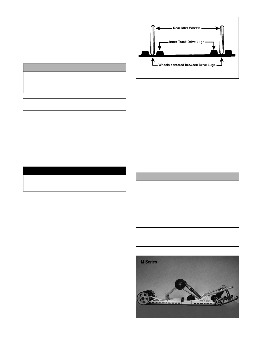
„NOTE: Proper track alignment is when the rear
idler wheels are equidistant from the inner drive
lugs on the inside surface of the track.

CHECKING

1. Using a shielded safety stand, raise the rear of the

snowmobile off the floor making sure the track is

free to rotate.

2. Start the engine and accelerate slightly. Use only

enough throttle to rotate the track several revolu-

tions. SHUT THE ENGINE OFF.

„NOTE: Allow the track to coast to a stop. Do not
apply the brake because it could produce inaccu-
rate alignment conditions.

3. When the track stops rotating, check the relation-

ship of the rear idler wheels and the inner track

drive lugs. If the distance from the idler wheels to

the inner drive lugs is the same on both sides, no

adjustment is necessary.

725-070A

4. On the side of the track which has the inner drive

lugs closer to the rear idler wheel, loosen the

adjusting bolt jam nut; then rotate the adjusting

bolt clockwise 1-1 1/2 turns.

„NOTE: If the track tension must be loosened, it
may be necessary to loosen the rear axle assem-
bly slightly.

5. Continue to check the track alignment and make

the necessary adjustments until proper alignment

is obtained.

6. After proper track alignment is obtained, lock the

jam nut against the axle housing.

„NOTE: Make sure correct track tension is main-
tained after adjusting track alignment.

„NOTE: Field test the track under actual condi-
tions and, after the field test, check track align-
ment and track tension; adjust as necessary.

Repair Procedure 3 -

Track/Rear Suspension

CM221A

! CAUTION

After proper track tension and alignment have been
attained, make certain that the rear axle assembly is
tightened to specifications or component damage
will occur.

! WARNING

The tips of the skis must be positioned against a
wall or similar object for safety. Keep hands, feet,
and clothing away from moving components.

! CAUTION

After proper track tension and alignment have been
attained, make certain that the rear axle assembly is
tightened to specifications or component damage
will occur.

7-73

7

This Track/Rear Suspension sub-section (Repair Pro-

cedure 3) has been organized so each procedure can be

completed individually and efficiently. Each sub-sec-

tion has (as necessary) Removing, Disassembling,

Cleaning and Inspecting, Assembling, and Installing

procedures. Some components may vary from model

to model. The technician should use discretion and

sound judgment when removing and installing compo-

nents.

„NOTE: Critical torque specifications are located
in Section 1 of this manual.

„NOTE: Some illustrations and photographs
used in this sub-section are used for clarity pur-
poses only and are not designed to depict actual
conditions.

Removing Skid Frame

„NOTE: Many service procedures can be per-
formed without removing the skid frame. Closely
observe the note introducing each sub-section for
this important information.

1. To avoid having the adjuster bushings binding dur-

ing loosening of the track, remove the rear idler

wheel caps and loosen the cap screws on the rear

axle.

0742-921

2. Loosen the jam nuts and two track-tension adjust-

ing bolts.

3. Place a support stand under the rear bumper; then

while holding the flared bushing, remove the rear

cap screws securing the skid frame to the tunnel.

Account for lock washers and flat washers.

„NOTE: The support stand should hold the
snowmobile level but not raised off the floor.

4. Remove the front cap screws securing the skid

frame to the tunnel. Account for a flat washer and

a lock washer.

5. Remove the support stand; then tip the snow-

mobile onto one side using a piece of cardboard to

protect against scratching. Remove the skid frame.

Wear Strips

REMOVING

„NOTE: The skid frame does not have to be
removed for this procedure; however, if wear strip
binding or slide rail damage has occurred, the skid
frame should be removed for this procedure (see
Removing Skid Frame in this sub-section).

1. Remove the machine screw and lock nut securing

the wear strip to the front of the slide rail.

CM222A

„NOTE: If the skid frame has been removed due
to difficulty in removing the wear strip, it may be
necessary to use a pipe wrench, start from either
end, and hook the edge of the wear strip with the
pipe wrench jaw and twist the wear strip off the
slide rail. Move the pipe wrench 7.5 cm (3 in.) and
again twist the wear strip off the rail. Repeat this
procedure until the wear strip is free of the rail.

2. Align the wear strip with the openings (windows)

in the track; then using a suitable driving tool,

drive the wear strip rearward off the slide rail.

739-884A

7-74

CLEANING AND INSPECTING

„NOTE: Whenever a part is worn excessively,
cracked, or damaged in any way, replacement is
necessary.

1. Clean the slide rail using parts-cleaning solvent

and compressed air.

2. Inspect the slide rail for cracks. If any cracks are

found, replace the slide rail.

3. Using a straightedge, inspect the slide rail for any

unusual bends. With the slide rail removed, place

the straightedge along the bottom surface of the

slide rail. If the rail is found to be bent, it must be

replaced.

AG536D

INSTALLING

„NOTE: Apply a light coat of grease to the slide
rail surface to aid in installing a new wear strip. If
there are any sharp edges on the lower portion of
the rail, use a file to remove them.

1. Align the wear strip with the openings (windows)

in the track and from the back, start the wear strip

onto the rail; then using a block of wood and a ham-

mer, drive the wear strip forward into position.

739-884A

2. Secure with a machine screw and lock nut. Tighten

to 60 in.-lb.

End Caps

„NOTE: The skid frame does not have to be
removed for this procedure.

REMOVING

1. Remove the lock nut, washers, and cap screw

securing the end cap.

CM222B

2. Using a hammer, tap the end cap off the rail.

CLEANING AND INSPECTING

„NOTE: Whenever a part is worn excessively,
cracked, or damaged in any way, replacement is
necessary.

1. Inspect the end cap area of the slide rail for cracks

and wear.

CM223A

2. Inspect the end cap for any signs of cracking or

wear.

! WARNING

Always wear an approved pair of safety glasses
when using compressed air.

7-75

7

MS290A

3. Clean both the slide rail area and the end cap.

Using compressed air, clean the areas of dirt and

gravel.

4. Inspect the cap screw for cracked, stretched, or

damaged threads. Use a new lock nut when assem-

bling.

INSTALLING

1. Position the end cap on the slide rail; then align the

hole in the end cap with the hole in the slide rail.

2. Secure with a cap screw, washers, and lock nut.

Tighten to 7 ft-lb.

Shock Pads

„NOTE: The skid frame does not have to be
removed for this procedure.

REMOVING

„NOTE: The shock pads should be removed only
if being replaced.

1. Remove the torx-head screws and lock nuts secur-

ing the rear shock pads to the slide rail.

2. Twist the push-nuts off the solid rivets securing

the front shock pads.

3. Remove the shock pads.

INSPECTING

„NOTE: Whenever a part is worn excessively,
cracked, or damaged in any way, replacement is
necessary.

1. Inspect the pads for damage or wear.

2. Inspect the cap screw holes in the slide rail for

damage or elongation.

INSTALLING

1. Place the front pads into position on the slide rail.

2. Secure the front pads with new push-nuts.

3. Place the rear pads into position on the slide rail.

4. Secure the rear pads with the torx-head screws and

lock nuts.

Rear Axle/

Slide Rail Idler Wheels

„NOTE: The skid frame must be removed for this
procedure (see Removing Skid Frame in this sub-
section).

DISASSEMBLING REAR AXLE

1. Remove the cap screw and large flat washer secur-

ing the outer rear idler wheel. Remove the outer

idler wheel from the shaft.

CM224A

2. Loosen the track adjusting bolts. Slide the outer

adjuster bushings off the axle.

CM225

3. Carefully slide the shaft out from the slide rails

and inner idler wheels. Account for the rear idler

wheel spacer and adjuster bushings.

! WARNING

Always wear an approved pair of safety glasses
when using compressed air.


Content   ..  126  127  128  129   ..