Snowmobile Arctic Cat (2008 year). Manual - part 126
7-64
MS182A
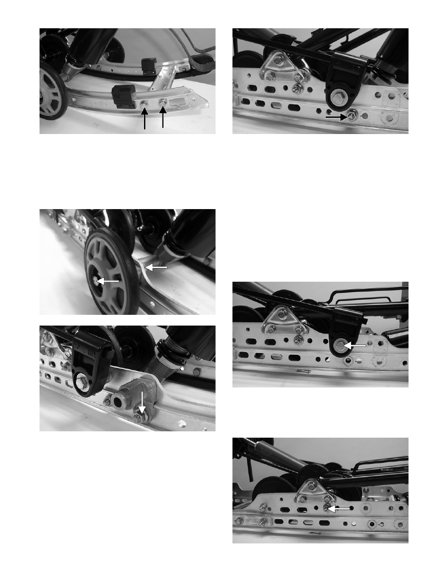
6. Remove the cap screws and lock nuts securing the
front outer idler wheels and the idler wheel mount-
ing blocks. Account for flat washers and spacer
washers.
NOTE: The idler wheel mounting block should
be removed only from the slide rail being replaced.
MS183A
MS184A
7. Remove the cap screw, washers, and lock nut
securing the front shock mount axle.
MS185A
NOTE: If it is necessary to remove the cap
screw for replacing the slide rail, install the cap
screw from the opposite side into the assembly to
secure components and aid in replacing the slide
rail.
NOTE: If not already done, remove the short
spring leg from the adjusting cam. Also, it is rec-
ommended that the top cap screw be removed
from the front shock absorber to aid in slide rail
installing.
8. Remove the cap screw and flat washer securing
the spring slide to the rail. Account for a spacer
and the slide block.
MS186A
9. Note the mounting location for installing pur-
poses; then remove the cap screw and lock nut
securing the front inner idler wheel assembly to
the slide rails.
MS187A