Snowmobile Arctic Cat (2008 year). Manual - part 119
7-36
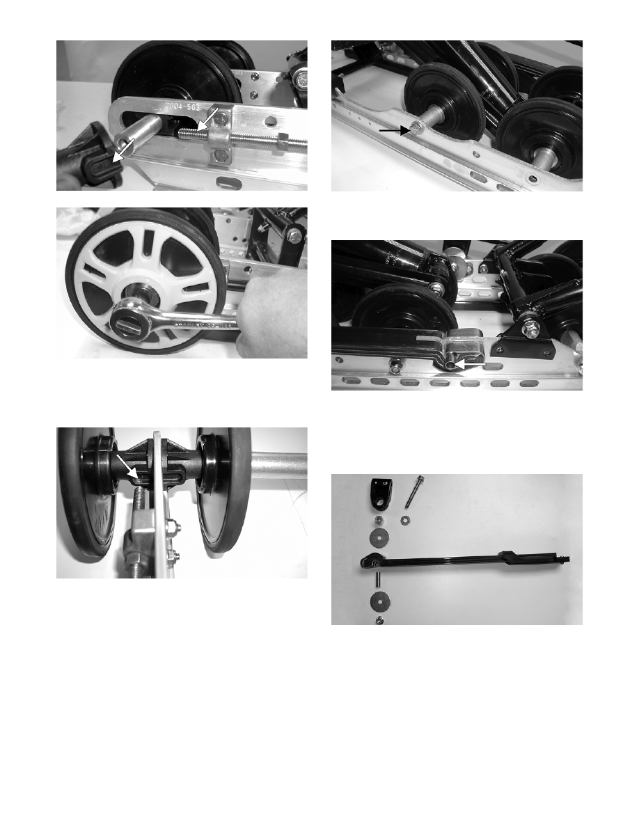
MS114A
FC194
NOTE: Care must be taken that the adjuster
bushing slot with the cap screw hole is aligned
properly with the adjuster bolt.
MS058A
NOTE: If applicable, install coupler block w/
bushing. Secure with cap screws and lock nuts.
Tighten securely.
6. Install the cap screw (coated with blue Loctite
#243) securing the rear inner idler wheel assembly
to the slide rail. Tighten only until snug.
NOTE: On the Bearcat 570, also install a cap
screw (coated with blue Loctite #243) securing the
rear-most inner idler wheel assembly to the slide
rail. Tighten only until snug.
MS111A
7. Place the overload spring with retaining clips and
bushing to the proper hole in the slide rail.
MS119A
8. Place the spring into the slide blocks; then place
the spring slide and slide block assembly into posi-
tion on the slide rail. Secure with a cap screw,
washer, spacer, two large flat washers, and a lock
nut. Tighten to 20 ft-lb.
MS108