Snowmobile Arctic Cat (2008 year). Manual - part 117


  Index      Snowmobiles / ATV     Snowmobile Arctic Cat - service manual 2008 year


Search            


Content   ..  115  116  117  118   ..


Snowmobile Arctic Cat (2008 year). Manual - part 117


7-28

Rear Shock Absorber 

and Shock Links

„NOTE: Before removing the skid frame by using
the Rear Suspension Spring Tool, remove the
spring from the adjusting cam.

„NOTE: The skid frame must be removed for this
procedure (see Removing Skid Frame in this sub-
section).

DISASSEMBLING

„NOTE: When removing center components from
the skid frame, it is advisable to loosen all cap
screws/lock nuts from one side of the slide rail to
make removing easier.

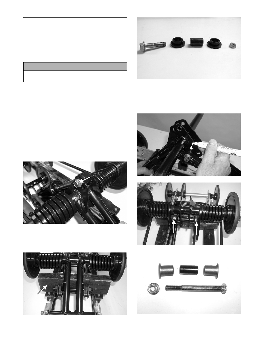
1. Disengage the shock absorber at the upper eyelet

and remove the shock absorber. Account for a

sleeve, cap screw, lock nut, and bushings.

MS089A

„NOTE: For ease of disassembling, it is advis-
able at this point to place a block of wood between
the idler arm and the overload springs.

MS090A

MS091

2. Mark the hole that the upper shock links are

mounted in for assembly purposes; then remove

the cap screw and lock nut securing the shock

links to the upper arm bracket. Account for all

mounting hardware.

MS076

MS092A

MS093

! CAUTION

Care must be taken when removing the spring from
the adjusting cam or damage or injury could result.

7-29

7

3. Note the hole location that the center inner idler

wheel/pivot assembly is in; then remove the cap

screw, flat washer, and lock nut securing the

assembly to the rails.

MS094A

4. Tap one side of the idler wheel/pivot assembly for-

ward until it clears the slide rails; then lift the

assembly upward and out from between the rails.

MS095

„NOTE: Lay components out in order as they are
removed.

5. With the idler wheel/pivot assembly removed,

remove the three spacers, an axle, and washers

from the pivot bracket.

6. Remove the cap screw, lock nut, and washer secur-

ing the shock rod links to the pivot arm. Account

for all components and mounting hardware.

MS097

CLEANING AND INSPECTING

„NOTE: Whenever a part is worn excessively,
cracked, or damaged in any way, replacement is
necessary.

1. Clean shock pivot and idler wheel axle in part-

cleaning solvent. Dry with compressed air.

2. Clean the idler wheel bearings with a clean cloth.

3. Closely inspect the pivot bracket arm and axles for

wear, bends, or damaged splines at either end.

4. Inspect the idler wheels for signs of cracking,

wear, or outer rubber separation from plastic

wheel.

5. Rotate the idler wheel bearings (by hand) and

inspect for any signs of binding or roughness.

6. If a bearing must be replaced, use this procedure.

A. Remove the snap ring.

B. Using a hydraulic press or suitable driving tool,

remove the bearing from the inside of the

wheel.

C. Press the new bearing (on its outer race) into

the idler wheel.

MS006A

D. Install the snap ring making sure the “sharp

side” is directed away from the bearing.

! WARNING

Always wear an approved pair of safety glasses
when using compressed air.

! CAUTION

Do not remove the bearing unless it is absolutely
necessary. The bearing will be damaged during
removal.

7-30

MS007A

7. Inspect the shock absorber for any signs of oil

leakage especially at the point where the shock

shaft enters the shock body.

8. Inspect the rubber shock bushings located in the

shock absorber eyelets for cracks or deterioration.

9. Inspect the shock absorber eyelet welds (at each

end) for any cracks or signs of separation.

10. Inspect the welds securing the eyelets of the shock

links for cracks or signs of separation. If either

condition exists, replace the shock link.

11. Inspect the axle surfaces for any signs of corro-

sion. If corrosion is found, lightly buff the surface

of the axle with #400 wet-or-dry sandpaper; then

apply a light coat of grease.

12. Inspect the pivot assembly for signs of cracks or

elongated holes.

ASSEMBLING

1. Secure the shock rod links (with axles) and the

lower end of the shock absorber to the idler wheel/

pivot assembly with the cap screw and lock nut.

Tighten securely.

MS096A

„NOTE: Do not over-tighten the shock absorber
cap screw as the shock eyelet must be free to
pivot.

2. Apply a thin coat of low-temperature grease to the

axle and slide the axle and spacer into the shock

pivot bracket. Have equal amounts of the axle

exposed on either side of the pivot bracket tube.

FC189

3. From each side of the pivot, install a washer, idler

wheel, washer, and spacer.

AG492D

4. Lower the idler wheel/pivot assembly down

between the rails. Align the axle with the mount-

ing hole (as noted during disassembly). Secure

with the cap screw and a new lock nut. Tighten to

40 ft-lb.

MS095

7-31

7

MS101

5. Position the shock links in the appropriate holes of

the idler arm brackets (as marked during disassem-

bling). Place a spacer between the center of the

brackets; then insert the link axles into the upper

shock link eyelets. Secure with a cap screw,

washer, and lock nut. Tighten securely.

MS081

6. Secure the shock absorber to the idler arm with

bushings, sleeve, lock nut, and a cap screw.

Tighten securely.

MS100

„NOTE: Do not over-tighten the shock absorber
cap screw as the shock eyelet must be free to
pivot.

7. Install the skid frame (see Installing Skid Frame in

this sub-section).

„NOTE:  It is advisable to install the rear arm springs
onto the adjuster blocks after the skid frame has been
installed.

Slide Rails

„NOTE: The skid frame must be removed for this pro-
cedure (see Removing Skid Frame in this sub-section).

REMOVING

„NOTE: When it is necessary to replace one or
both slide rails, it is recommended that one slide
rail be removed at a time. The remaining slide rail
will then hold the rail supports, axles, and brackets
in their correct assembly order. Always mark the
mounting hole locations during disassembly to
speed up the assembly process and to prevent any
damage. This method is much quicker than to
completely disassemble the entire skid frame. To
replace either rail, use the following procedure.

1. Remove the end cap from the slide rail. Account

for a cap screw, lock nut, and two flat washers.

MS016A

2. Remove the machine screw and lock nut securing

the wear strip to the front of the slide rail.

MS017B

3. Using a suitable driving tool, drive the wear strip

off the rail.


Content   ..  115  116  117  118   ..