Snowmobile Arctic Cat (2008 year). Manual - part 118
7-32
AG510D
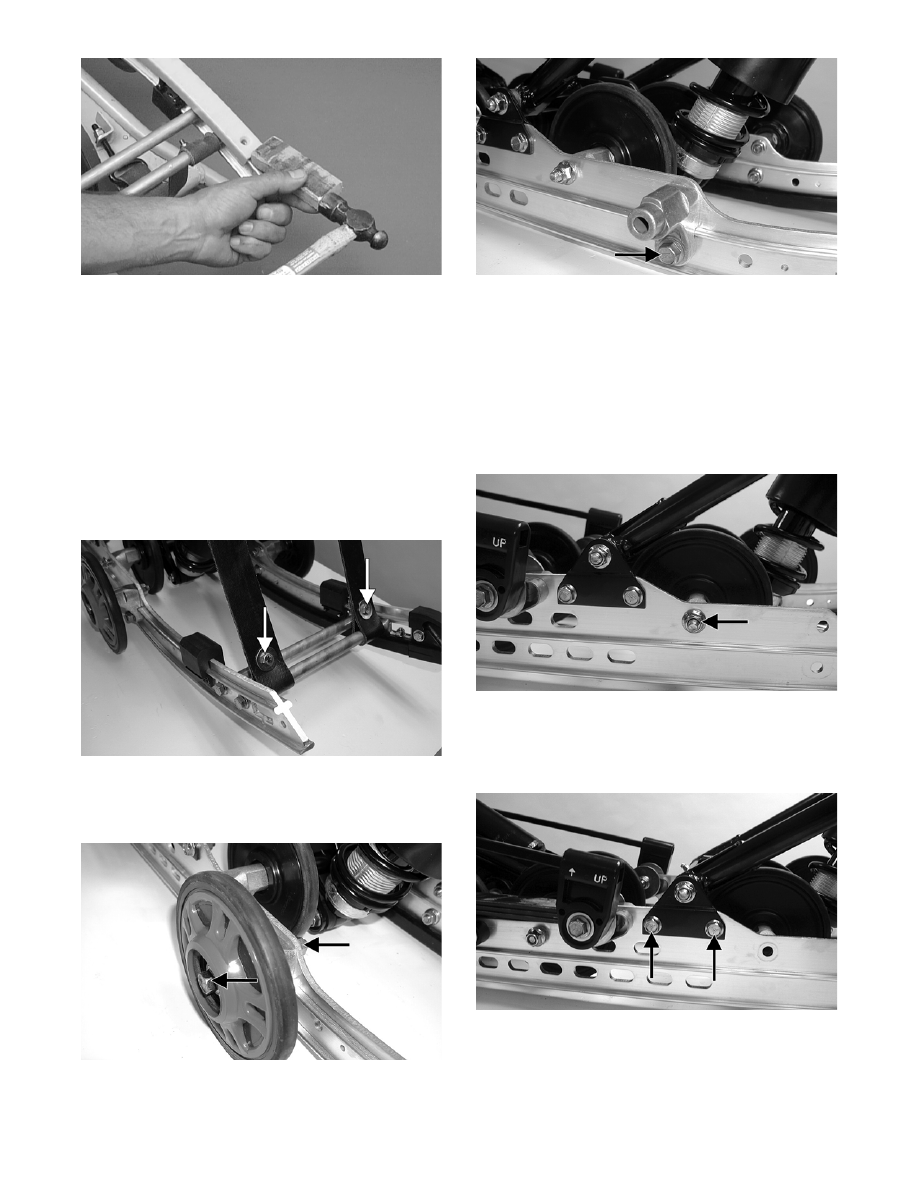
NOTE: If binding of the wear strip occurs, use a pipe
wrench, start from either end, and hook the edge
of the wear strip with the pipe wrench jaw and
twist the wear strip off the slide rail. Move the pipe
wrench 7.5 cm (3 in.) and again twist the wear strip
off the rail. Repeat this procedure until the wear
strip is free of the rail.
4. Remove the cap screws and lock nuts securing the
front arm limiter straps to the rail support.
5. Remove the cap screws securing the rail supports
to the slide rail.
MS102A
6. Remove the cap screws and lock nuts securing the
front outer idler wheel and the idler wheel mount-
ing block. Account for flat washers.
MS103A
MS104A
NOTE: If not already done, remove the short
spring leg from the adjusting cam. Also, it is rec-
ommended that the cap screw be removed from
the front shock absorber to the front arm to aid in
slide rail installing.
7. Remove the cap screw and lock washer securing
the front inner idler wheel assembly to the slide
rail.
MS105A
8. Note the mounting position of the front arm
mounting bracket; then remove the cap screws
securing the front arm mounting bracket. Account
for lock nuts.
MS106A
NOTE: If it is necessary to remove the cap
screw for replacing the slide rail, install the cap
screw from the opposite side into the assembly to
secure the components and aid in replacing the
slide rail.