Index Snowmobiles / ATV Snowmobile Arctic Cat - service manual 2008 year
Search
Content .. 110 111 112 113 ..
Snowmobile Arctic Cat (2008 year). Manual - part 112
7-8
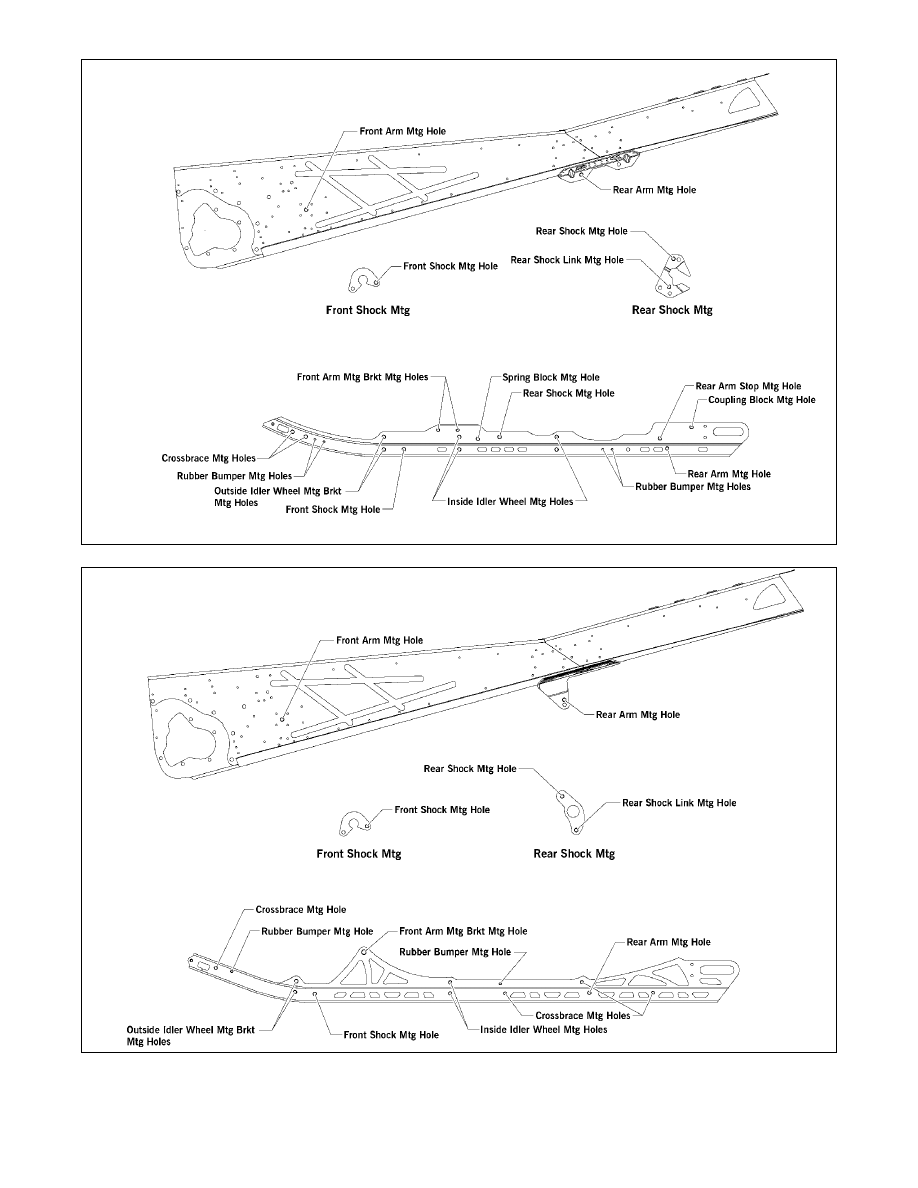
0742-848
0742-847
Crossfire Models
M-Series Models