Snowmobile Arctic Cat (2008 year). Manual - part 108
6-76
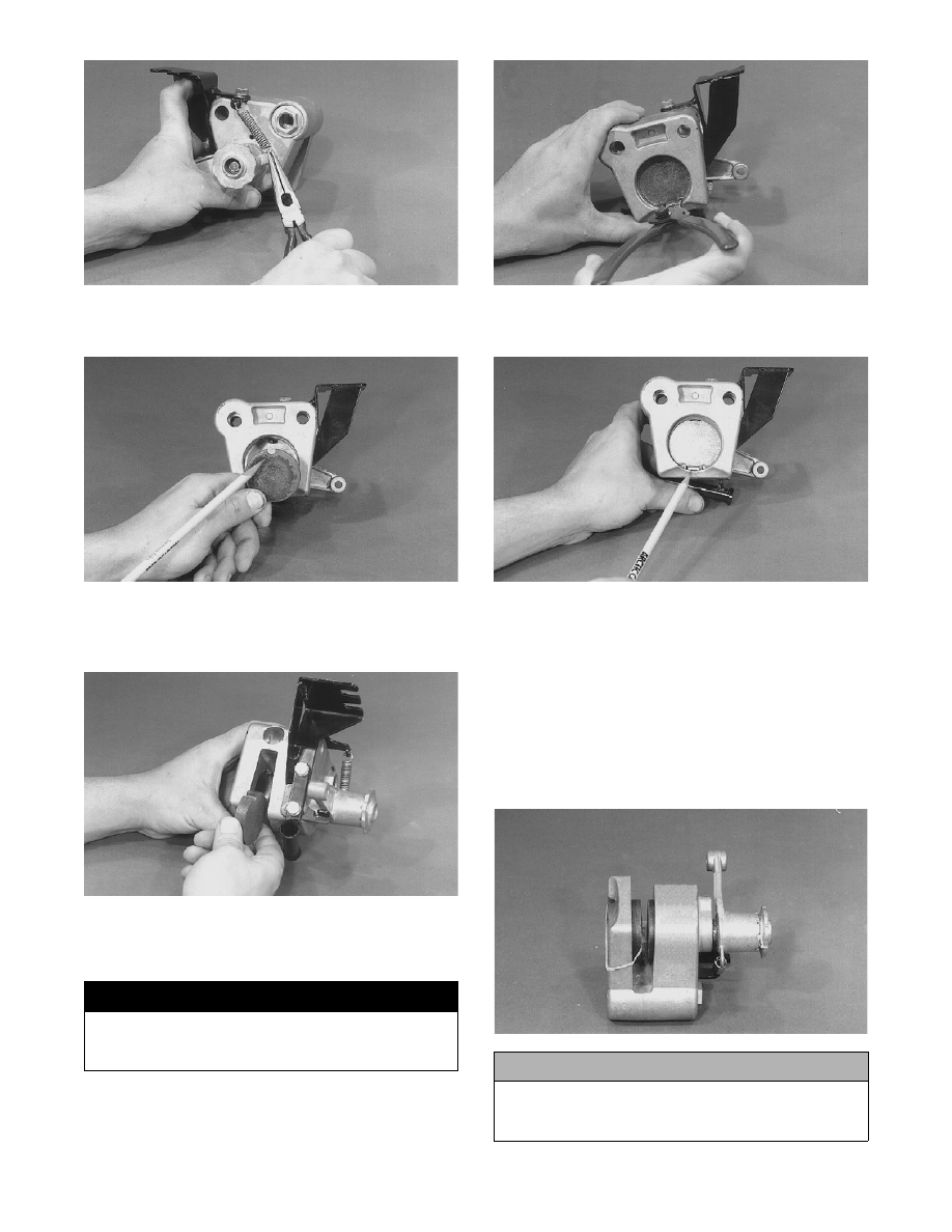
AF351A
7. Install the brake piston making sure that the slot in
the piston aligns with the roll pin in the caliper.
AF325A
8. Install the movable (thick) brake pad into the cali-
per making sure that the slot in the pad aligns with
the roll pin in the caliper.
AF320
9. Install the snap ring into the caliper making sure
that the sharp edge of the snap ring faces out and
the opening faces down.
AF318A
10. Install the brake pad support plate with the large
tab located in the opening of the snap ring.
AF322
11. Install the stationary (thin) brake pad into the cali-
per making sure the slot in the pad aligns with the
small tab on the support plate. Use a rubber band
to hold the pad and plate in position.
INSTALLING
1. With the rubber band holding the stationary pad
and support plate in position, install the caliper
assembly over the brake disc. Remove the rubber
band.
AF321A
! WARNING
Be sure the snap ring is fully seated. Personal injury
may result if the snap ring isnt seated properly
within the slot of the caliper.
! CAUTION
Make sure that the brake pads are properly posi-
tioned in the caliper or damage to the brake system
will result.