Snowmobile Arctic Cat (2008 year). Manual - part 107


  Index      Snowmobiles / ATV     Snowmobile Arctic Cat - service manual 2008 year


Search            


Content   ..  105  106  107  108   ..


Snowmobile Arctic Cat (2008 year). Manual - part 107


6-72

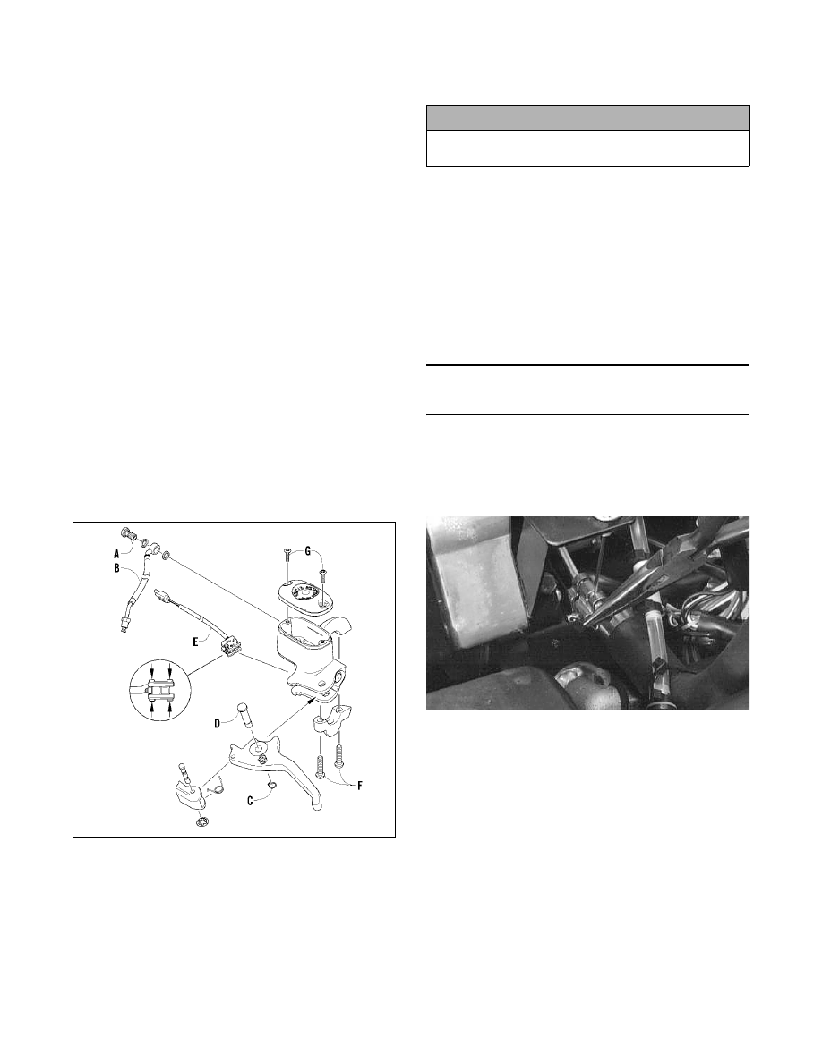
4. Using a small screwdriver, compress the tabs of

the brakelight switch (E) to release it from the

master cylinder.

5. Remove the two torx-head screws (F) and clamp

securing the brake reservoir to the handlebar; then

place a towel over the reservoir and remove the

assembly from the handlebar.

INSPECTING

„NOTE: Whenever a part is worn excessively,
cracked, or damaged in any way, replacement is
necessary.

1. Inspect the snap ring and pin securing the brake

lever for wear or damage; then inspect the brake

lever for cracks or damage.

2. Inspect the master cylinder reservoir and cover for

cracks and leakage.

„NOTE: The master cylinder is a non-serviceable
component. If any wear or damage is detected, the
master cylinder must be replaced.

3. Inspect the brake fluid hose for cracks, deteriora-

tion, and the condition of the fittings (threaded and

compression).

INSTALLING

0742-152

1. Position the brake assembly on the handlebar.

Secure with two torx-head screws (F) and clamp;

tighten securely.

2. Install the brake fluid hose (B) to the master cylin-

der with the banjo-fitting bolt (A) and two new

crush washers. Tighten securely.

3. Install the brakelight switch (E) to the master cyl-

inder.

4. Install the brake lever; then secure with pin (D)

and snap ring (C).

5. Place the reservoir cover onto the master cylinder

reservoir; then secure with the two torx-head

screws (G).

6. Bleed the brake system (see Bleeding Brake Sys-

tem in this sub-section).

Brake System

(Panther 370)

REMOVING

1. Remove the cotter pin, washer, pin, and clevis

from the brake actuator arm.

AF297D

2. Remove the recoil starter rope from the brake

cable bracket.

3. Loosen the jam nut on the brake cable and remove

the cable from the bracket.

4. Loosen and remove the two mounting cap screws

(account for the front alignment ball) and remove

the brake caliper.

! CAUTION

Always use new crush washers when installing the
brake fluid hose.

6-73

6

AF460D

AF293D

DISASSEMBLING

1. Remove the snap ring on the stationary side of the

caliper.

AF318A

2. Remove the brake pad support plate.

AF356

3. Remove the stationary brake pad.

AF354

4. Remove the movable brake pad.

5. Remove the brake piston.

AF353

6. Remove the brake actuator arm return spring.

AF351A

7. Loosen and remove the three cap screws securing

the brake cable bracket and remove the bracket.

6-74

AF326

8. Remove the brake actuator arm assembly from the

caliper.

AF283

9. Pull out on the quick-adjust knob and turn counter-

clockwise to remove.

AF328

10. Remove the adjustment bolt and spring from the

quick-adjust knob.

AF333

11. On the rear of the caliper, loosen and remove the

jam nut, washer, spring, and ball assembly.

AF331

CLEANING AND INSPECTING

„NOTE: Whenever a part is worn excessively,
cracked, or damaged in any way, replacement is
necessary.

1. Using a calipers, measure the stationary and mov-

able brake pads. The movable brake pad thickness

must exceed 12.7 mm (0.500 in.). The stationary

brake pad thickness must exceed 6.22 mm

(0.245 in.).

0730-504

„NOTE: When replacing brake pads, always
replace both pads as a set.

2. Wash all brake components with parts-cleaning

solvent and dry thoroughly.

6-75

6

3. Inspect all brake components for signs of wear,

fatigue, cracks, or stripped threads.

4. Inspect the spring for cracks, stretching, or

unusual bends.

5. Inspect the brake cable for any signs of fraying or

broken strands. Replace as needed.

ASSEMBLING

1. In the rear mounting hole of the caliper, tempo-

rarily install the mounting cap screw. In sequence,

install the alignment ball (apply a small amount of

grease to the ball), spring, washer, and jam nut.

Turn the jam nut in until slight spring pressure is

felt; then remove the mounting cap screw.

AF331

2. Apply Arctic Cat All-Temperature Grease to the

actuator shaft.

AF327

3. Insert the adjustment bolt with spring and quick-

adjust knob into the actuator assembly and turn in

2 or 3 turns.

AF329

4. With the actuator shaft arm in the 11 o’clock posi-

tion (located over the front mounting hole), install

the actuator shaft into the brake caliper assembly.

AF338

5. Place the brake cable bracket and rope guide into

position and secure with the three cap screws and

lock washers.

AF352A

6. Install the brake arm actuator return spring.


Content   ..  105  106  107  108   ..