Snowmobile Arctic Cat (2008 year). Manual - part 102


  Index      Snowmobiles / ATV     Snowmobile Arctic Cat - service manual 2008 year


Search            


Content   ..  100  101  102  103   ..


Snowmobile Arctic Cat (2008 year). Manual - part 102


6-52

ZJ196

ZJ197

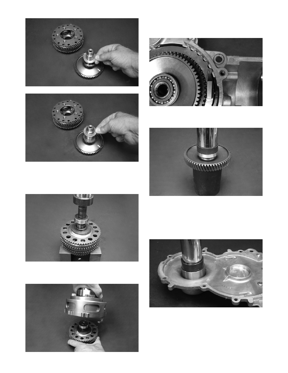
5. Position the planetary gear assembly onto the

transfer gear shaft; then install the spacer washer.

Using a suitable press, install the inner bearing

onto the transfer gear shaft.

ZJ208

6. Install the output gear assembly into the slider

assembly until the inner bearing is properly seated.

ZJ194

7. With the alignment notches of the slider and gear

case properly positioned, install the slider/output

gear assembly into the gear case.

ZJ201

8. Using a suitable bearing press, install the outer

bearing onto the transfer gear shaft.

ZJ199

9. Using a suitable bearing press and fixture, install

the input shaft bearing to the gear case; then install

the oil seal.

„NOTE: A light coat of grease must be applied to
the seal prior to installing.

ZJ202

6-53

6

ZJ204

10. Using a suitable press, install the input shaft to the

gear case cover.

MS349

11. Install the first retaining ring onto the shift fork

shaft; then install a new oil seal.

„NOTE: It is advisable to apply a film of grease to
the oil seal prior to installing.

12. With the alignment marks properly positioned,

install the shift fork arm to the shaft. Secure the

arm with the remaining retaining ring.

ZJ301A

13. Install the slider blocks to the shift fork assembly;

then install the fork assembly into the slider and

gear case.

ZJ205

„NOTE: Make sure to install the slider blocks with
the rounded end up and the raised edges facing to
the outside of each other.

ZJ302

14. Apply a 1/8-in. bead of Loctite Sealant to the

sealing surfaces of the gear case.

ZJ207

15. With the dowel pins in place, install the cover to

the gear case and secure with the torx-head cap

screws; then in a crisscross pattern, tighten to 12

ft-ft.

! CAUTION

Care must be taken not to allow silicone sealant into
the cap screw holes and dowel pin holes or damage
to the gear case may occur when tightening the cap
screws.

6-54

0742-196

16. On electronic reverse models, install the shift actu-

ator and secure with the torx-head cap screw.

Tighten to 43 in.-lb. Install the gear indicator

switch; then tighten securely.

FS269A

17. Pour 354 ml (12 fl oz) of Arctic Cat Synthetic

ACT Drive Fluid into the drain/fill hole; then

install the plug. Tighten to 12 ft-lb.

INSTALLING GEAR CASE

1. Using a Scotch Brite pad, clean the gear case/drive

unit seal-mating surface on the track driveshaft;

then thoroughly wipe clean.

„NOTE: Prior to placing the gear case onto the
driveshaft, apply a light coat of Arctic Cat Low-
Temp Snowmobile Grease to the internal splines
of the track driveshaft.

2. Align the gear case output shaft with the splines of

the track driveshaft and position the gear case onto

the mounting studs. Making sure the sensor wire

does not become pinched under the gear case,

push inward on the gear case until it is seated.

3. Using a soft hammer, lightly tap inward on the

gear case to ensure that is fully seated to the chas-

sis.

4. Loosely secure the gear case by first installing the

six lock nuts and finger tighten; then install a torx-

head cap screw and the two remaining lock nuts.

Tighten all the nuts to 20 ft-lb.

0742-017

„NOTE: When tightening the nuts to the proper
torque factor, it is advisable to begin tightening the
nuts located on the bottom of the gear case and
working upward until all nuts are tightened to the
proper torque factor.

5. Install the torque bumper behind the engine

mounting bracket; then carefully work it into place

with the aid of a flat-blade screwdriver.

MS299

„NOTE: Use of a quality silicone spray will aid in
installing the torque bumper.

6. Connect shift actuator harness (A) and gear indica-

tor swich harness (B); then install the left-side

footrest cover and secure with the screws.

! CAUTION

Do not add more or less than the recommended
amount of drive fluid to the gear case or damage to
the gear case will occur.

6-55

6

FS268A

7. Slide the driven pulley onto the driven shaft mak-

ing sure alignment washers are in place (if applica-

ble).

8. Secure the driven pulley with components and

hardware as noted in removing. Tighten to 32 ft-

lb.

ZJ250A

9. Install the drive belt.

„NOTE: For installing drive belt, see Removing/
Installing Drive Belt (ACT Roller Driven Pulley) in
this section.

10. Install the 16 mm cap screw (coated with blue

Loctite #243) securing the driveshaft to the gear

case output shaft; then tighten to 70 ft-lb.

742-020A

11. Install the drive belt guard and side panels.

„NOTE: If the track was loosened to aid in remov-
ing the gear case, tighten track to proper tension
and alignment.

Brake System

(Hydraulic)

CHECKING BRAKE LEVER TRAVEL

1. Compress the brake lever fully.

„NOTE: Do not pump the brake lever as it will pro-
duce an inaccurate reading.

2. Measure the distance between the brake lever and

the handlebar. The distance must be greater than

2.54 cm (1 in.).

740-159B

741-328C

3. If the distance is less than specified, check the

brake fluid level (see Checking and Adding Brake

Fluid in this sub-section), inspect for leakage, and

check the brake pads (see appropriate Checking

and Replacing Brake Pads in this sub-section).

! WARNING

Do not operate the snowmobile if the distance
between the compressed brake lever and handlebar
is less than 2.54 cm (1 in.). Brake loss may occur.
Brake loss can result in severe personal injury.


Content   ..  100  101  102  103   ..