Snowmobile Arctic Cat (2008 year). Manual - part 101


  Index      Snowmobiles / ATV     Snowmobile Arctic Cat - service manual 2008 year


Search            


Content   ..  99  100  101  102   ..


Snowmobile Arctic Cat (2008 year). Manual - part 101


6-48

ZJ195

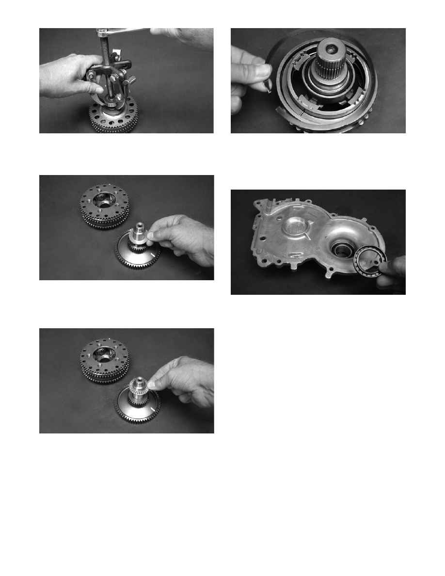
12. Remove the transfer gear from the planetary gear

assembly and account for the thrust washer and

thrust bearing.

ZJ196

„NOTE: For assembling purposes, note that the
thrust bearing is positioned between the thrust
washer and the gear assembly.

ZJ197

13. Remove the retaining ring and thrust washer

securing the slider housing assembly to the output

shaft assembly.

ZJ200

14. Using a suitable puller, remove the bearing from

the output shaft.

15. Using a suitable seal removing tool, remove the

input/output shaft seals from the gear case.

ZJ204

CLEANING AND INSPECTING GEAR 

CASE

„NOTE: Whenever a part is worn excessively,
cracked, or damaged in any way, replacement is
necessary.

„NOTE: The planetary gear assembly is a non-ser-
viceable component. If any damage or wear is
detected, it must be replaced.

1. Wash the gear case halves in parts-cleaning sol-

vent.

2. Inspect the gear case halves for scoring, pitting,

scuffing, or any imperfections in the casting.

3. Inspect all threaded areas for damaged or stripped

threads.

4. Inspect the bearing areas for cracks or excessive

bearing movement. If evidence of excessive bear-

ing movement is noted, replace the component.

5. Inspect the sealing surfaces of the gear case halves

for trueness.

6. Wash the unsealed gear case bearings in parts-

cleaning solvent.

6-49

6

7. Inspect the input shaft/transfer gear bearings for

wear, scoring, scuffing, damage, or discoloration.

Rotate the bearings. Bearings must rotate freely

and must not bind or feel rough. If any abnormal

condition is noted, replace the bearing.

„NOTE: The output shaft bearing is a non-service-
able component. If any damage or binding is
noted, the output shaft assembly must be
replaced.

8. Apply a light film of Arctic Cat Synthetic ACT

Drive Fluid to the unsealed bearings prior to

assembling.

REMOVING DRIVE SPROCKETS

„NOTE: The drive sprockets must be removed
from the gear case end of the driveshaft.

ZJ216A

1. For installing purposes, scribe a line on the drive-

shaft (A) next to the drive sprocket for proper

alignment; then scribe a line on the driveshaft

directly in line with the timing arrows (B) on the

drive sprockets for proper sprocket timing.

MS357A

2. Using a suitable press positioned against the ten-

sion-collar of the drive sprocket (located on the

gear case) and of the driveshaft, press the drive

sprockets off the driveshaft.

ZJ217

ZJ218A

Cleaning and Inspecting

„NOTE: Whenever a part is worn excessively,
cracked, or damaged in any way, replacement is
necessary.

1. Thoroughly wash all metallic components in parts-

cleaning solvent. Dry using compressed air.

2. Wash all non-metallic components with soap and

water.

3. Inspect the driveshaft for damaged splines or

stripped threads.

4. Inspect the seals for any breaks or damage.

5. Inspect the track for cuts, gouges, or wear.

6. Inspect the brake disc for wear or cracks.

7. Inspect the track drive sprockets for wear or dam-

age.

! CAUTION

Always press against the tension-collar of the drive
sprockets or damage to the components will occur.

6-50

INSTALLING DRIVE SPROCKETS

„NOTE: The drive sprockets must be installed on
the gear case end of the driveshaft.

ZJ216A

„NOTE: Prior to installing the sprockets onto the
driveshaft, it is advisable to lightly chamfer the
inside edge of the sprocket to avoid binding.

MS362

1. Properly align the scribed line on the driveshaft

(from removing) with the timing arrow on the

drive sprocket; then slide the sprocket onto the

driveshaft as far as it will go.

MS360A

2. Using a suitable press and fixture, press the drive-

shaft into the sprocket until it aligns with the line

scribed in removing.

MS361A

3. Slide the remaining sprocket onto the driveshaft

making sure the timing arrow/lines (from remov-

ing) are aligned; then using the press/fixture, press

the sprocket to the remaining alignment line.

MS359A

4. Using a calipers, measure distances between the

sprockets and from the sprockets to each end of

the driveshaft for proper location (see illustra-

tions).

0742-367

! CAUTION

Always press against the tension-collar of the drive
sprockets or damage to the components will occur.

Crossfire

6-51

6

0742-366

MS364

ASSEMBLING GEAR CASE

1. With the narrow, raised edge of the seal (A) facing

outward and using an appropriate seal installation

tool, install the oil seal into the output shaft open-

ing of the gear case.

ZJ303A

„NOTE: Grease must be applied to the seal prior
to installing.

ZJ304

„NOTE: Always install the seal with the wide,
raised edge of the seal facing against the seal sur-
face of the gear case.

2. Place the output shaft assembly into position in the

slider housing; then secure the assembly to the

housing with the thrust washer and retaining ring.

ZJ200

3. Using a suitable bearing press, install the bearing

onto the ring gear.

ZJ199

4. In order, install the thrust washer and then the

thrust bearing onto the transfer gear shaft.

M-Series


Content   ..  99  100  101  102   ..