Snowmobile Arctic Cat (2008 year). Manual - part 97


  Index      Snowmobiles / ATV     Snowmobile Arctic Cat - service manual 2008 year


Search            


Content   ..  95  96  97  98   ..


Snowmobile Arctic Cat (2008 year). Manual - part 97


6-32

ZJ250A

15. Install the drive belt.

„NOTE: For installing drive belt, see Removing/
Installing Drive Belt (ACT Roller Driven Pulley) in
this section.

16. Place the access panels into position and secure

with existing hardware.

17. Check the track for alignment and recommended

tension; then tighten the cap screws securely (see

Section 7).

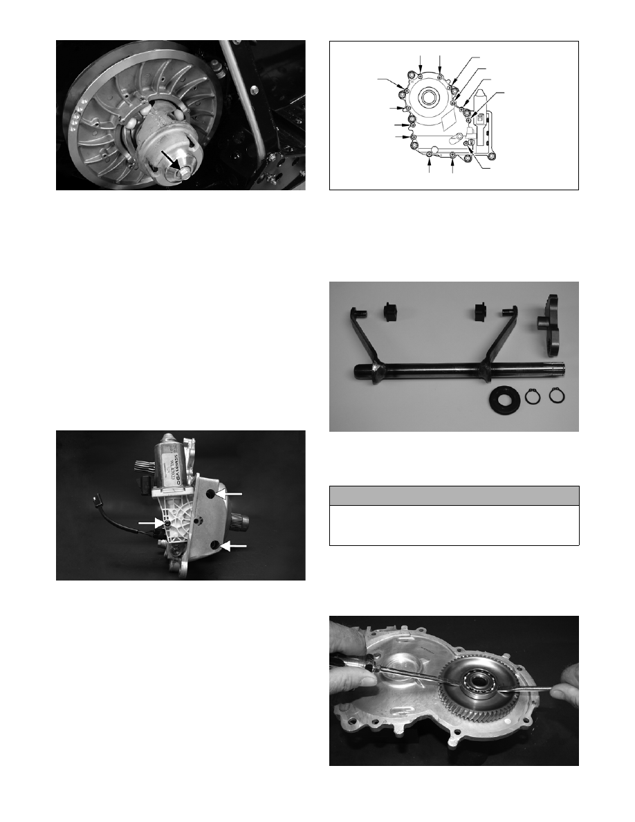
DISASSEMBLING GEAR CASE

1. On electronic reverse models, remove the three

torx-head cap screws securing the shift actuator to

the gear case and remove the actuator; then

remove the gear indicator switch.

ZJ186A

2. Remove the torx-head cap screws securing the

gear case cover to the gear case assembly; then

insert two flat-blade screwdrivers into the slots on

the gear case. Working back and forth, pry the

cover up and off the gear case.

742-195B

3. Drain the gear case fluid into a suitable container.

4. Remove the shift fork assembly; then remove the

retaining ring securing the shift fork arm to the

shaft and remove the arm. Account for the retain-

ing rings, O-ring, and slider blocks.

ZJ300

„NOTE: For assembling purposes, note the posi-
tion of the slider blocks on the shift fork arm.

5. Secure the gear case cover in a suitable clamping

device; then using two flat-blade screwdrivers

from opposite sides of the cover bearing, evenly

pry the input shaft bearing up and off the shaft.

ZJ189

! CAUTION

If the input shaft bearing is removed, always replace
it with a new one or severe component damage may
occur.

6-33

6

6. With a cap screw threaded into the input shaft and

using a soft hammer, drive the input shaft out of

the gear case cover.

ZJ190

7. Using a suitable bearing press and fixture, press

the input shaft bearing out of the gear case cover.

Account for a bearing and a seal.

ZJ191

MS331

8. Secure the gear case in a suitable clamping device;

then using the procedure from step 5, remove the

outer bearing from the transfer gear.

ZJ192

9. Place the gear case on its side; then using a soft

hammer, tap the output shaft until the slider and

output gear assembly come free of the gear case.

ZJ193

10. Remove the output gear assembly from the slider

housing.

ZJ194

11. Using a suitable bearing puller, remove the inner

bearing from the transfer gear assembly. Account

for a spacer washer.

! CAUTION

If any transfer gear bearings are removed, always
replace them with new ones or severe component
damage may occur.

6-34

ZJ195

12. Remove the transfer gear from the planetary gear

assembly and account for the thrust washer and

thrust bearing.

ZJ196

„NOTE: For assembling purposes, note that the
thrust bearing is positioned between the thrust
washer and the gear assembly.

ZJ197

13. Remove the retaining ring and thrust washer

securing the slider housing assembly to the output

shaft assembly.

ZJ200

14. Using a suitable puller, remove the bearing from

the output shaft.

15. Using a suitable seal removing tool, remove the

output/input shaft seals from the gear case.

ZJ204

CLEANING AND INSPECTING GEAR 

CASE

„NOTE: Whenever a part is worn excessively,
cracked, or damaged in any way, replacement is
necessary.

„NOTE: The planetary gear assembly is a non-ser-
viceable component. If any damage or wear is
detected, it must be replaced.

1. Wash the gear case halves in parts-cleaning sol-

vent.

2. Inspect the gear case halves for scoring, pitting,

scuffing, or any imperfections in the casting.

3. Inspect all threaded areas for damaged or stripped

threads.

4. Inspect the bearing areas for cracks or excessive

bearing movement. If evidence of excessive bear-

ing movement is noted, replace the component.

5. Inspect the sealing surfaces of the gear case halves

for trueness.

6. Wash the unsealed gear case bearings in parts-

cleaning solvent.

6-35

6

7. Inspect the input shaft/transfer gear bearings for

wear, scoring, scuffing, damage, or discoloration.

Rotate the bearings. Bearings must rotate freely

and must not bind or feel rough. If any abnormal

condition is noted, replace the bearing.

„NOTE: The output shaft bearing is a non-service-
able component. If any damage or binding is
noted, the output shaft assembly must be
replaced.

8. Apply a light film of Arctic Cat Synthetic ACT

Drive Fluid to the unsealed bearings prior to

assembling.

REMOVING DRIVE SPROCKETS

„NOTE: The drive sprockets must be removed
from the gear case end of the driveshaft.

ZJ216A

1. For installing purposes, scribe a line on the drive-

shaft (A) next to the drive sprocket for proper

alignment; then scribe a line on the driveshaft

directly in line with the timing arrows (B) on the

drive sprockets for proper sprocket timing.

MS357A

2. Using a suitable press positioned against the ten-

sion-collar of the drive sprocket (located on the

gear case) and of the driveshaft, press the drive

sprockets off the driveshaft.

ZJ217

ZJ218A

Cleaning and Inspecting

„NOTE: Whenever a part is worn excessively,
cracked, or damaged in any way, replacement is
necessary.

1. Thoroughly wash all metallic components in parts-

cleaning solvent. Dry using compressed air.

2. Wash all non-metallic components with soap and

water.

3. Inspect the driveshaft for damaged splines or

stripped threads.

4. Inspect the seals for any breaks or damage.

5. Inspect the track for cuts, gouges, or wear.

6. Inspect the brake disc for wear or cracks.

7. Inspect the track drive sprockets for wear or dam-

age.

! CAUTION

Always press against the tension-collar of the drive
sprockets or damage to the components will occur.


Content   ..  95  96  97  98   ..