Snowmobile Arctic Cat (2008 year). Manual - part 98


  Index      Snowmobiles / ATV     Snowmobile Arctic Cat - service manual 2008 year


Search            


Content   ..  96  97  98  99   ..


Snowmobile Arctic Cat (2008 year). Manual - part 98


6-36

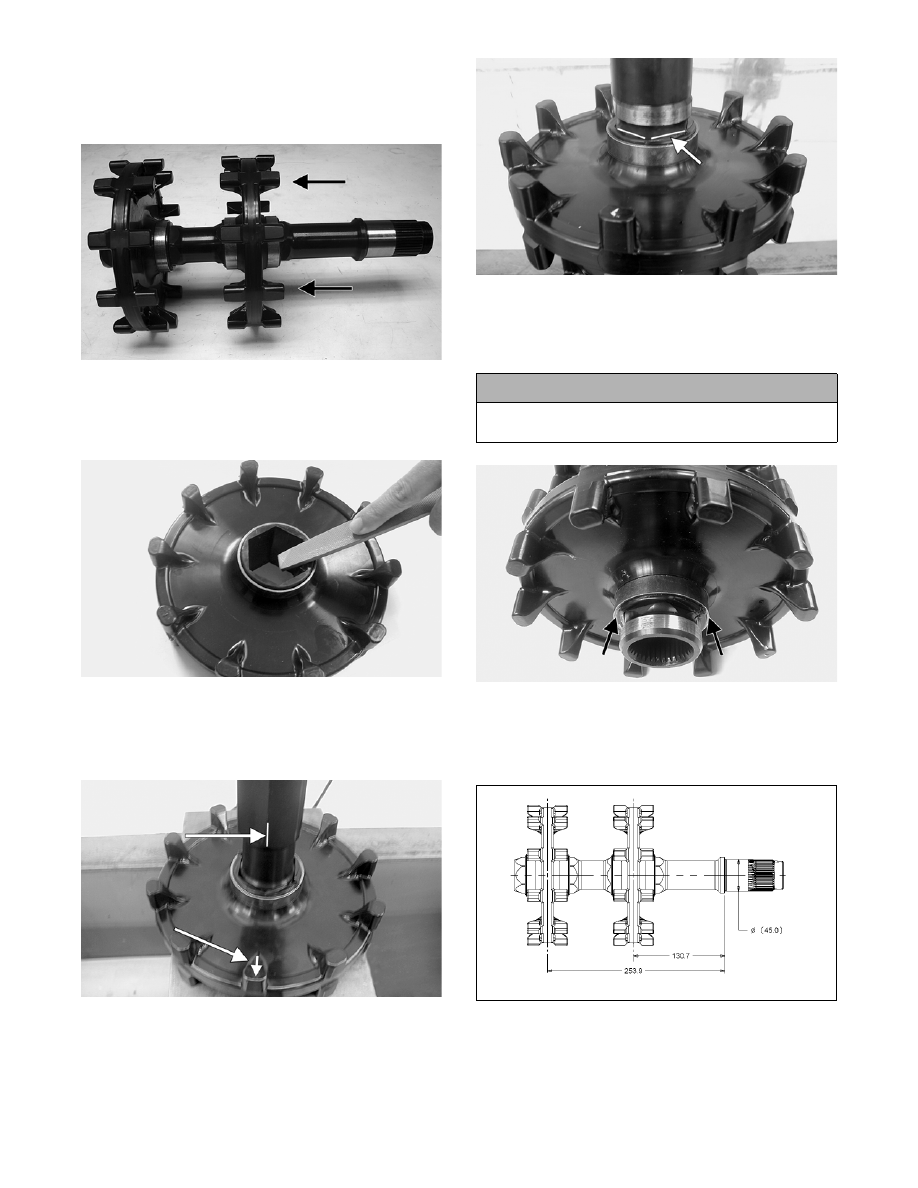
INSTALLING DRIVE SPROCKETS

„NOTE: The drive sprockets must be installed on
the gear case end of the driveshaft.

ZJ216A

„NOTE: Prior to installing the sprockets onto the
driveshaft, it is advisable to lightly chamfer the
inside edge of the sprocket to avoid binding.

MS362

1. Properly align the scribed line on the driveshaft

(from removing) with the timing arrow on the

drive sprocket; then slide the sprocket onto the

driveshaft as far as it will go.

MS360A

2. Using a suitable press and fixture, press the drive-

shaft into the sprocket until it aligns with the line

scribed in removing.

MS361A

3. Slide the remaining sprocket onto the driveshaft

making sure the timing arrow/lines (from remov-

ing) are aligned; then using the press/fixture, press

the sprocket to the remaining alignment line.

MS359A

4. Using a calipers, measure distances between the

sprockets and from the sprockets to each end of

the driveshaft for proper location (see illustra-

tions).

0742-042

! CAUTION

Always press against the tension-collar of the drive
sprockets or damage to the components will occur.

6-37

6

MS364

ASSEMBLING GEAR CASE

1. With the narrow, raised edges of the seal (A) fac-

ing outward and using an appropriate seal installa-

tion tool, install the oil seal into the output shaft

opening of the gear case.

„NOTE: Grease must be applied to the seal prior
to installing.

ZJ303A

ZJ304

„NOTE: Always install the seal with the wide,
raised edge of the seal facing against the seal sur-
face of the gear case.

ZJ305A

2. Place the output shaft assembly into position in the

slider housing; then secure the assembly to the

housing with the thrust washer and retaining ring.

ZJ200

3. Using a suitable bearing press, install the bearing

onto the ring gear.

ZJ199

4. In order, install the thrust washer and then the

thrust bearing onto the transfer gear shaft.

6-38

ZJ196

ZJ197

5. Position the planetary gear assembly onto the

transfer gear shaft; then install the spacer washer.

Using a suitable press, install the inner bearing

onto the transfer gear shaft.

ZJ208

6. Install the output gear assembly into the slider

assembly until the inner bearing is properly seated.

ZJ194

7. With the alignment notches of the slider and gear

case properly positioned, install the slider/output

gear assembly into the gear case.

ZJ201

8. Using a suitable bearing press, install the outer

bearing onto the transfer gear shaft.

ZJ199

9. Using a suitable bearing press and fixture, install

the input shaft bearing to the gear case; then install

the oil seal.

„NOTE: A light coat of grease must be applied to
the seal prior to installing.

ZJ202

6-39

6

ZJ204

10. Using a suitable press, install the input shaft to the

gear case cover.

MS349

11. Install the first retaining ring onto the shift fork

shaft; then install a new oil seal.

„NOTE: It is advisable to apply a film of grease to
the oil seal prior to installing.

12. With the alignment marks properly positioned,

install the shift fork arm to the shaft. Secure the

arm with the remaining retaining ring.

ZJ301A

13. Install the slider blocks to the shift fork assembly;

then install the fork assembly into the slider and

gear case.

ZJ205

„NOTE: Make sure to install the slider blocks with
the rounded end up and the raised edges facing to
the outside of each other.

ZJ302

14. Apply a 1/8-in. bead of Loctite Sealant to the

sealing surfaces of the gear case.

ZJ207

15. With the dowel pins in place, install the cover to

the gear case and secure with the torx-head cap

screws; then in a crisscross pattern, tighten to 12

ft-lb.

! CAUTION

Care must be taken not to allow silicone sealant into
the cap screw holes and dowel pin holes or damage
to the gear case may occur when tightening the cap
screws.


Content   ..  96  97  98  99   ..