Snowmobile Arctic Cat (2008 year). Manual - part 95
6-24
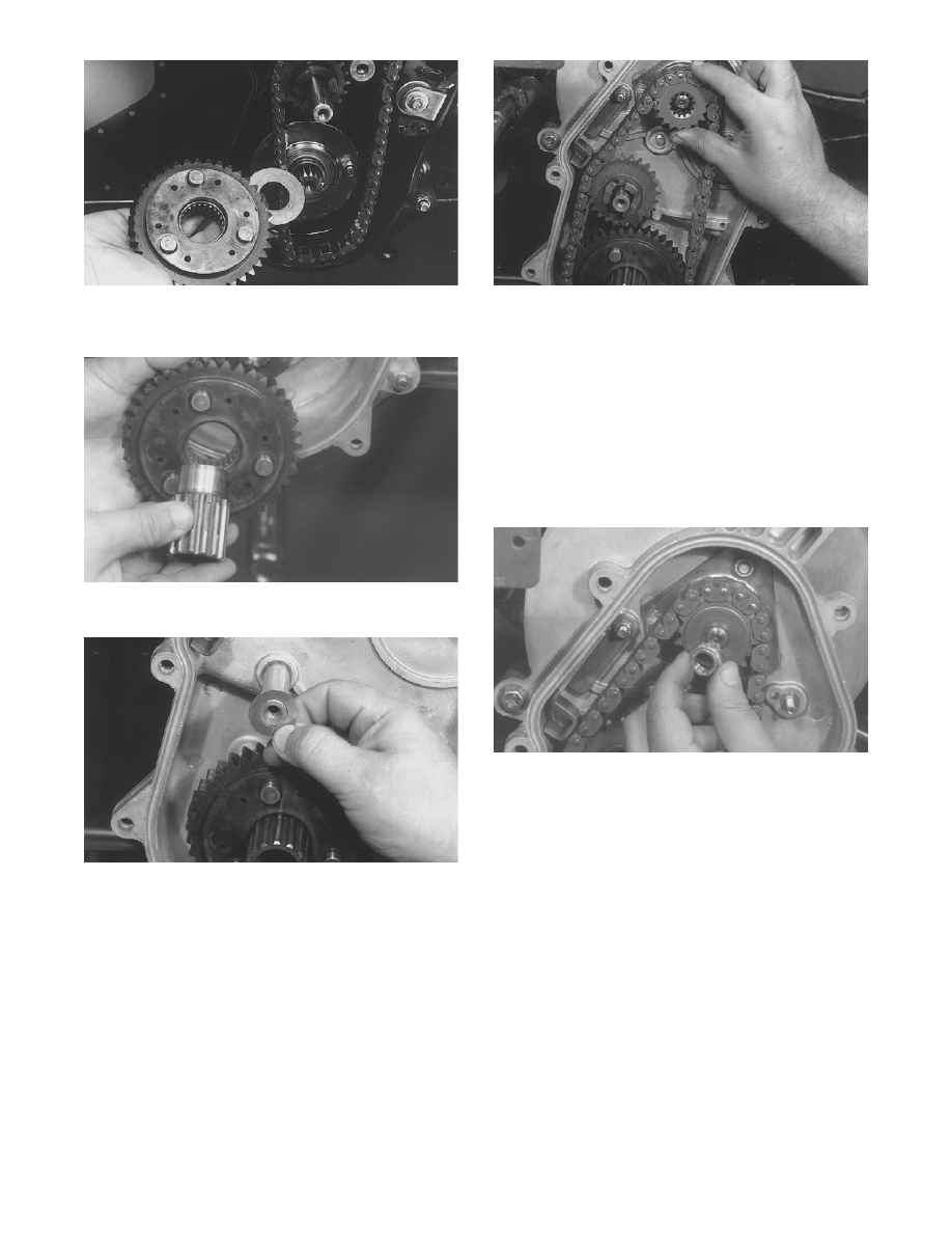
AF090
12. Install the bottom sprocket and driveshaft exten-
sion.
AF427
13. Position one shim washer on the idler gear shaft.
AF430
14. Position the chain around the lower reverse
sprocket; then place the idler sprocket and top
sprocket into the chain. Slide sprockets into posi-
tion on the idler shaft and driven shaft.
AF441
NOTE: If the chain tension is too tight to allow
installation of the top sprocket, remove the PTO-
side driven shaft bearing. This will allow the driven
shaft to be lifted at the PTO-side and will allow the
sprocket to slide onto the splined end of the driven
shaft.
15. Secure the top sprocket with a spring washer (with
the high side directed away from the sprocket) and
lock nut (coated with green Loctite #609). Tighten
the lock nut to 35 ft-lb.
AF432
NOTE: If the PTO-side driven shaft bearing was
removed to make the sprocket installation easier,
install the bearing and flange plate. Lock the bear-
ing collar by driving it in the direction of rotation to
lock the collar to the bearing and shaft. Tighten the
collar set screw.
16. Place the rubber alignment pin into position in the
idler sprocket; then slide the outer idler gear on the
shaft. Install shim washer on the shaft.