Snowmobile Arctic Cat (2008 year). Manual - part 94
6-20
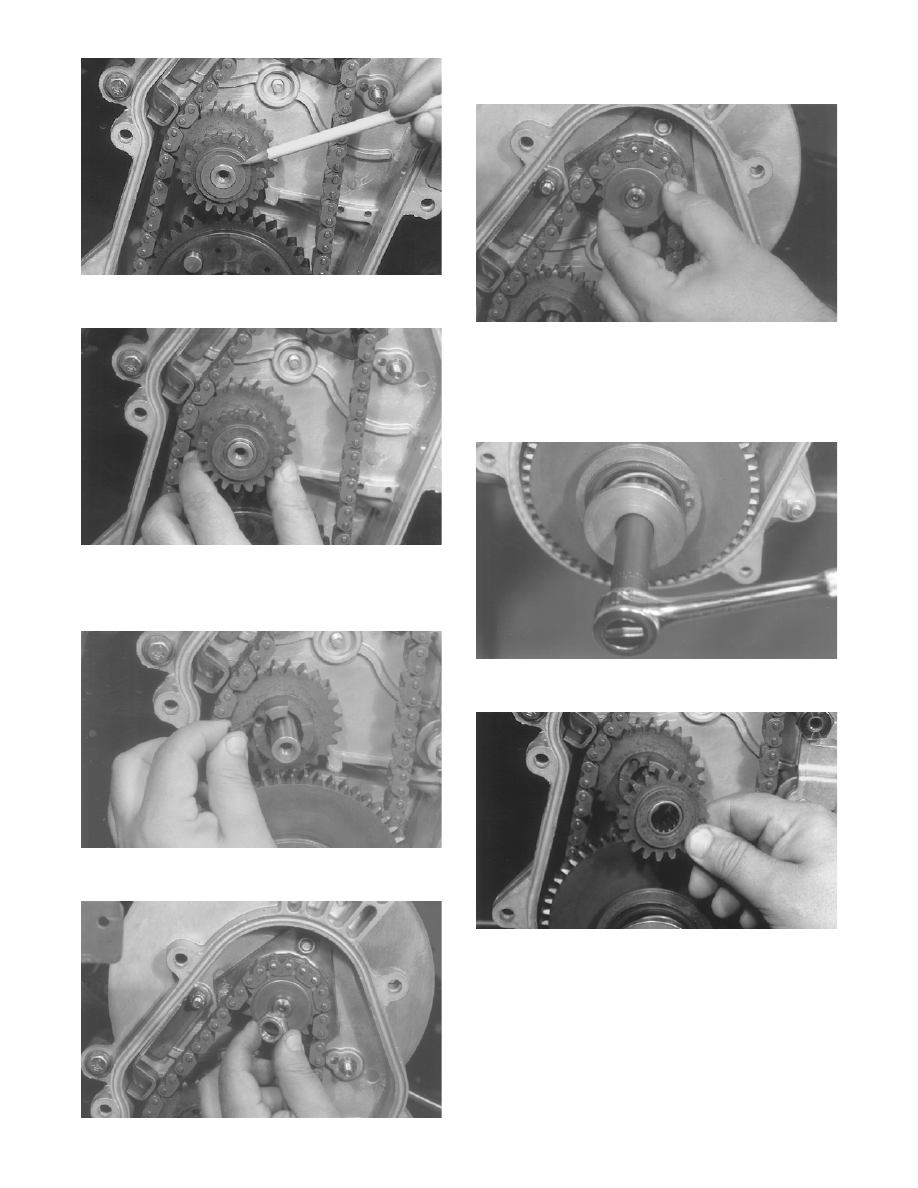
AF436
10. Remove the outer idler sprocket from the shaft.
AF437
11. Slide the small rubber alignment pin from the face
of the inner idler sprocket and place in safe loca-
tion until assembly.
AF439
12. Remove the lock nut securing the top sprocket.
AF432
13. Remove the spring washer in front of the top
sprocket.
AF444
14. Set the brake lever lock. Remove the cap screw
and large washer securing the bottom sprocket.
NOTE: The bottom sprocket cap screw and
washer are spring loaded.
AF428
15. Remove the reverse gear.
AF442
16. Remove the top sprocket, chain, and idler gear.
Account for one shim washer located behind the
idler gear.