Snowmobile Arctic Cat (2008 year). Manual - part 92
6-12
4. Using a stiff ruler centered between the drive
clutch and driven pulley, push down on the drive
belt just enough to remove all slack. Note the
amount of deflection on the ruler at the bottom of
the straightedge. The deflection should be within
the range of 25-31 mm (1-1 1/4 in.).
NOTE: Push down on the belt with the ruler only
until the bottom of the belt flexes upward; then
read the amount of deflection.
5. To correct drive belt deflection, washers can be
removed or added between the stationary and
movable sheaves of the driven pulley.
NOTE: If the drive belt deflection is above specifi-
cations, the snowmobile will bog and lack power at
clutch engagement. For good performance, proper
belt deflection is critical.
6. Secure the belt guard.
ACT Roller Driven Pulley
(Crossfire/F-Series/M-Series)
REMOVING
1. Remove the drive belt.
NOTE: For removing drive belt, see Removing/
Installing Drive Belt (ACT Roller Driven Pulley) in
this section.
2. Using a 9/16-in. socket and extension, remove the
cap screw securing the driven pulley to the driven
shaft.
3. Slide the driven pulley off the driven shaft.
NOTE: Account for and remove any alignment
washers. These washers must be used during
installing.
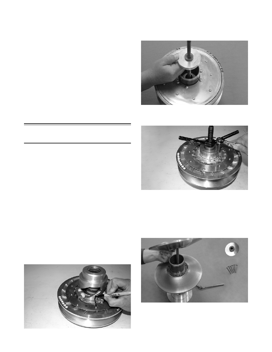
DISASSEMBLING
1. Prior to disassembling, mark the driven pulley
sheaves and torque bracket.
CM060
2. Place the driven pulley on the Driven Pulley Com-
pressor; then install the compressor flange spacer
and wing nut and compress the driven pulley
spring.
FS090
3. Remove the torx-head cap screws securing the
movable sheave to the pulley.
CM061
NOTE: To loosen the torx-head cap screws, it
may be necessary to insert a torx-bit and strike
each screw with a hammer.
4. Release the compression of the spring by remov-
ing the wing nut; then remove the movable sheave.
Account for the spacer (retainer).
FS093