Snowmobile Arctic Cat (2008 year). Manual - part 90
6-4
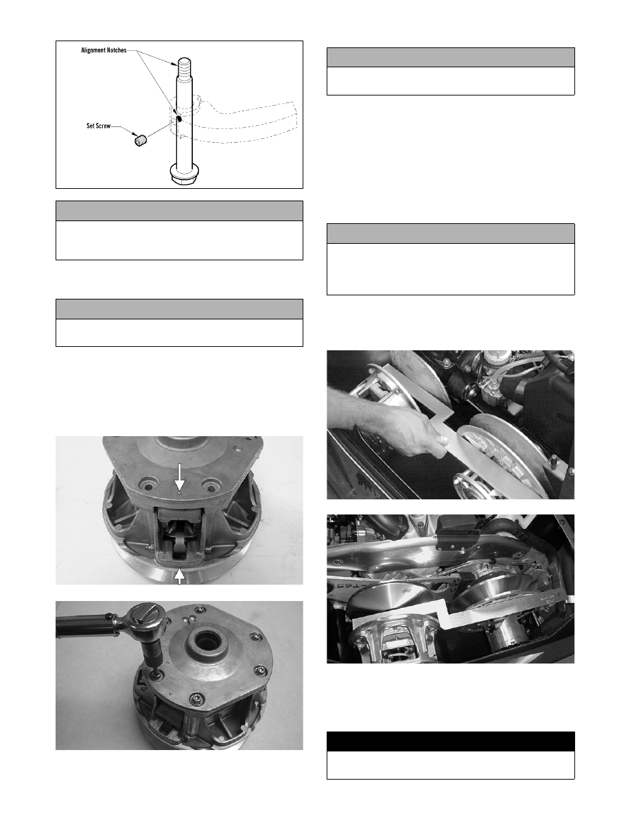
739-040A
3. Secure the cam arm pins with new lock nuts and
tighten to 19 in.-lb.
4. Place the spring and cover into position making
sure the timing mark on the cover is properly
aligned; then compress the spring and install the
machine screws coated with blue Loctite #243 and
lock washers. In a crisscross pattern, tighten
evenly to 10 ft-lb.
MS402A
FC091
Installing
NOTE: Before installing the drive clutch, be sure
to wipe both the crankshaft taper and clutch
mounting taper clean using a clean towel.
1. Place the drive clutch into position on the crank-
shaft and secure with the appropriate cap screw
and lock washer. Tighten to 55 ft lb.
2. Check alignment between the drive clutch and
driven pulley (see appropriate Drive Clutch/
Driven Pulley in this section).
AF468D
MS390
3. Install the drive belt. Check drive belt deflection
(see appropriate Drive Clutch/Driven Pulley in
this section). Secure the belt guard and install the
plug in the belly pan.
! CAUTION
It is critical that green Loctite #620 be applied to the
set screw holes in the cam arms or component dam-
age may occur.
! CAUTION
When installing cam arms, always use new lock nuts
and cam arm set screws.
! CAUTION
Care must be taken when installing the cover not to
damage the bushing.
! CAUTION
When installing the drive clutch, do not tighten the
cap screw with any kind of impact tool. Tighten cap
screw using a hand torque wrench only. Failure to
do so could result in stationary sheave damage.
! WARNING
Never operate the engine without the belt guard/side
panel secured.