Snowmobile Arctic Cat (2008 year). Manual - part 31


  Index      Snowmobiles / ATV     Snowmobile Arctic Cat - service manual 2008 year


Search            


Content   ..  29  30  31  32   ..


Snowmobile Arctic Cat (2008 year). Manual - part 31


2-61

2

„NOTE: Check to be sure the mark on the control
arm is aligned with alignment mark on the oil-
injection pump boss in the full-open position. If the
marks are not aligned, adjust synchronization by
loosening the jam nuts on the adjuster. Rotate the
jam nuts/adjuster nut until proper alignment is
attained. Tighten jam nuts.

„ NOTE: When the cable/linkage adjusting nut is
adjusted correctly, the throttle lever will move
approximately 1/8 in. before the oil-injection pump
arm begins to move.

6. Remove the oil bleed plug from the oil injection

pump. When oil flows from pump free of air bub-

bles and the hose is full of oil, install the oil bleed

plug and tighten.

„NOTE: It is advisable to place a cloth beneath the
oil-injection pump to contain any oil spilled during
the bleeding process.

7. With the throttle cable and fuel lines properly

routed, install the flange clamps to the intake

flanges; then install the carburetors and secure

with the clamps.

FZ006

8. Install the headlight support bracket and secure the

bracket with the cap screws and lock nuts.

„NOTE: The headlight support bracket must be
installed before the engine is secured.

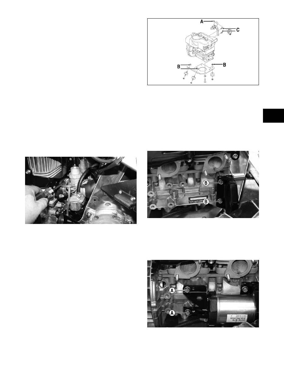
9. Install the rear MAG-side engine mounting

bracket to the engine with the two cap screws (C).

Tighten to 20 ft-lb; then position the engine to the

chassis mounts.

0742-672A

10. Install the three lock nuts (B) securing the engine

plate to the chassis; then install the cap screw (A)

securing the rear MAG-side engine bracket to the

chassis. Tighten to 20 ft-lb.

11. Carefully work the carburetor boots over the

intake bore of the carburetors.

12. Install the PTO-side starter motor bracket to the

engine and secure with the two cap screws (B).

Tighten to 20 ft-lb. 

FZ023A

13. With the rubber dampers in place on the brackets,

install the starter motor and the MAG-side bracket

to the engine with the two cap screws (A) and

tighten to 20 ft-lb. Route the ground cable up

through the engine plate and secure with cap

screw. Tighten securely.

FZ024A

14. Apply a thin coat of high-temperature silicone

sealant to each exhaust port; then install the

exhaust gaskets.

2-62

15. Apply a thin coat of high-temperature silicone

sealant to the mating surfaces of the exhaust mani-

fold; then install the exhaust manifold and secure

with six nuts. Tighten the nuts to 15 ft-lb.

FZ015

16. With the recoil rope placed in the roller, install the

rope retaining roller to the rear MAG-side engine

bracket with the cap screw washer and lock nut

and tighten securely.

FZ020A

17. Place the recoil starter into position and secure the

starter with the cap screws. In a crisscross pattern,

tighten to 8 ft-lb.

FZ002

„NOTE: Install the engine ground wire to the
proper recoil cap screw as noted during disassem-
bly.

FZ011A

18. With the U-nut clip in place, install the heat shield

and secure the shield with the cap screws and lock

nuts.

FZ016A

„NOTE: Be sure that the engine ground wire is on
the cap screw securing the heat shield to the sus-
pension mounting bracket; then secure the nega-
tive battery cable to the battery. 

19. Install the snubber bracket; then secure the bracket

to the chassis with the cap screw and two lock

nuts. Tighten to 20 ft-lb.

FZ007A

20. Secure the wiring harness to the chassis with the

wiring harness clamp, cap screw, and lock nut.

Tighten securely.

2-63

2

FZ012A

21. Install the grommets into the spark plug opening

of the engine shroud; then connect the spark plug

wires.

22. Place the drive clutch into position on the crank-

shaft and secure with the cap screw and lock

washer. Tighten to 55 ft-lb.

„NOTE: Before installing the drive clutch, be sure
to wipe both the crankshaft taper and clutch
mounting taper clean using a clean towel.

FZ018

23. Install the alignment washers (if applicable); then

install the driven pulley on the gear case input

shaft. Tighten the cap screw to 32 ft-lb.

FZ021

FZ019

24. Check drive clutch/driven pulley alignment (see

Section 6). Install the drive belt. Check belt deflec-

tion. Secure the belt guard.

„NOTE: Make sure the rubber exhaust bumper is
in position on the close-off cover before installing
the expansion chamber.

FZ017A

25. Install the exhaust resonator and secure to the

upper frame with the washer, cap screw, and lock

nut.

26. Place gaskets on the resonator and exhaust mani-

fold; then install the expansion chamber. Secure

the chamber to manifold and upper frame with the

springs.

„NOTE: When installing the exhaust manifold
springs, the long hook portion of the spring must
be attached to the exhaust manifold or premature
spring failure will result.

! CAUTION

When installing the drive clutch, do not tighten the
clutch cap screw with any kind of impact tool.
Tighten cap screw using a hand torque wrench only.
Failure to do so could result in stationary sheave
damage.

2-64

27. Place the console into position on the headlight

support bracket (do not secure the console with the

torx-head screws at this time); then connect the

console/main harness plug-in.

28. Connect the battery; then install and close the left-

side and right-side access panels and the hood.

29. Start the engine and warm up to operating temper-

ature; then verify that all components are function-

ing properly and that coolant is circulating through

the cooling system properly.

30. Verify the tightening torque of the drive clutch.

31. Secure the console to the steering support with the

torx-head screws and tighten the screws securely;

then close the left-side and right-side access panels

and close the hood.

741-722A

Engine - 

Crossfire 500/600 - 

M-Series 600

This engine servicing sub-section has been organized

to show a progression for the complete servicing of the

Arctic Cat 500 cc/600 cc (Crossfire/M-Series) engines.

For consistency purposes, this sub-section shows a

complete and thorough progression; however, for effi-

ciency it may be preferable to remove the engine as a

complete assembly, to remove and disassemble only

those components which need to be addressed, and to

service only those components. Also, some compo-

nents may vary from model to model. The technician

should use discretion and sound judgment.

„NOTE: Critical torque specifications can be
found in Section 1 of this manual.

„NOTE: Some illustrations and photographs used
in this section are used for clarity purposes only
and are not designed to depict actual conditions.

SPECIAL TOOLS

A number of special tools must be available to the

technician when performing service procedures in this

engine section.

„NOTE: Special tools are available from the Arctic
Cat Service Parts Department.

Table of Contents

Removing .............................................................. 2-65
Disassembling ....................................................... 2-68
Servicing Top-Side Components........................... 2-73
Cleaning and Inspecting........................................ 2-77
Measuring Critical Components ............................ 2-80
Assembling............................................................ 2-83
Installing ................................................................ 2-90

! CAUTION

Never run the engine with the hood harness discon-
nected or damage to the electrical system will result.

! CAUTION

After running the engine to the proper operating tem-
perature, shut the engine off; then open the hood
and access panels and inspect for any signs of cool-
ant, gasoline, or oil leakage.

! CAUTION

If the engine had a major overhaul or if any major
component was replaced, proper engine break-in
procedures must be followed (see Section 1). If the
proper engine break-in procedures are not followed,
severe engine damage may result.

Description

p/n

Ball Hone

0644-292

Drive Clutch Puller

0644-207

Drive Clutch Spanner Wrench

0644-136

Driven Pulley Puller

0644-468

Flywheel Spanner Wrench

0144-007

Flywheel Puller

0744-040

Flywheel Pulley Insert

0644-179

Medium Extractor Nut

0643-074

Piston Pin Puller

0644-328

Surface Plate

0644-016

Water Pump Bearing and Seal Tool Kit

0644-502

Vacuum Pump

0644-131

V Blocks

0644-022


Content   ..  29  30  31  32   ..