Snowmobile Arctic Cat (2008 year). Manual - part 29
2-53
2
2. Insert a snap gauge into each piston-pin bore; then
remove the gauge and measure it with a microme-
ter. The diameter measurement must be within
18.002-18.010 mm (0.7087-0.7090 in.). Take two
measurements to ensure accuracy.
AC092
CONNECTING-ROD SMALL END
BORE
1. Insert a snap gauge into each connecting-rod small
end bore; then remove the gauge and measure it
with a micrometer.
AN061
2. The diameter measurement must be within
23.003-23.011 mm (0.9056-0.9059 in.).
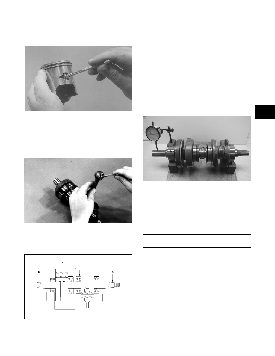
CRANKSHAFT RUNOUT
0742-727
1. Using the V Blocks, support the crankshaft on the
surface plate.
NOTE: The V blocks should support the crank-
shaft on the outer bearings.
2. Mount a dial indicator and base on the surface
plate. Position the indicator contact point against
the crankshaft location point A (PTO-end) from
the crankshaft end. Zero the indicator and rotate
the crankshaft slowly. Note the amount of crank-
shaft runout (total indicator reading).
NOTE: For runout location point specifications,
see Crankshaft Runout Specifications in Section 1
of this manual.
3. Position the indicator contact point against the
crankshaft location point B (MAG-end) from the
crankshaft end. Zero the indicator and rotate the
crankshaft slowly. Note the amount of crankshaft
runout (total indicator reading).
FC046
4. Position the indicator contact point against the
crankshaft at location point C (center). Zero the
indicator and rotate the crankshaft slowly. Note
the amount of crankshaft runout (total indicator
reading).
5. If runout exceeds 0.05 mm (0.002 in.) at any of the
checkpoints, the crankshaft must be either
straightened or replaced.
Assembling Engine
NOTE: The use of new gaskets and seals is rec-
ommended when assembling the engine.
NOTE: Before the engine is assembled, clean the
threads of the cap screws and the threaded areas
of the engine where Loctite will be used.
NOTE: When the use of a lubricant is indicated,
use Arctic Cat 50:1 Injection Oil.