Snowmobile Arctic Cat (2008 year). Manual - part 22


  Index      Snowmobiles / ATV     Snowmobile Arctic Cat - service manual 2008 year


Search            


Content   ..  20  21  22  23   ..


Snowmobile Arctic Cat (2008 year). Manual - part 22


2-25

2

MD0246

Cleaning and Inspecting 

Engine

„NOTE: Whenever a part is worn excessively,
cracked, or damaged in any way, replacement is
necessary.

CYLINDER HEAD

1. Using a non-metallic carbon removal tool, remove

any carbon buildup from the combustion chambers

being careful not to nick, scrape, or damage the

combustion chambers or the sealing surfaces.

2. Inspect the spark-plug holes for any damaged

threads.

3. Inspect the cylinder head for flatness using a

straightedge and a feeler gauge. Acceptable

warpage must not exceed 0.05 mm (0.002 in.).

„NOTE: If the warpage exceeds specification,
resurface the cylinder head using procedures
identified in step 4.

MD2491

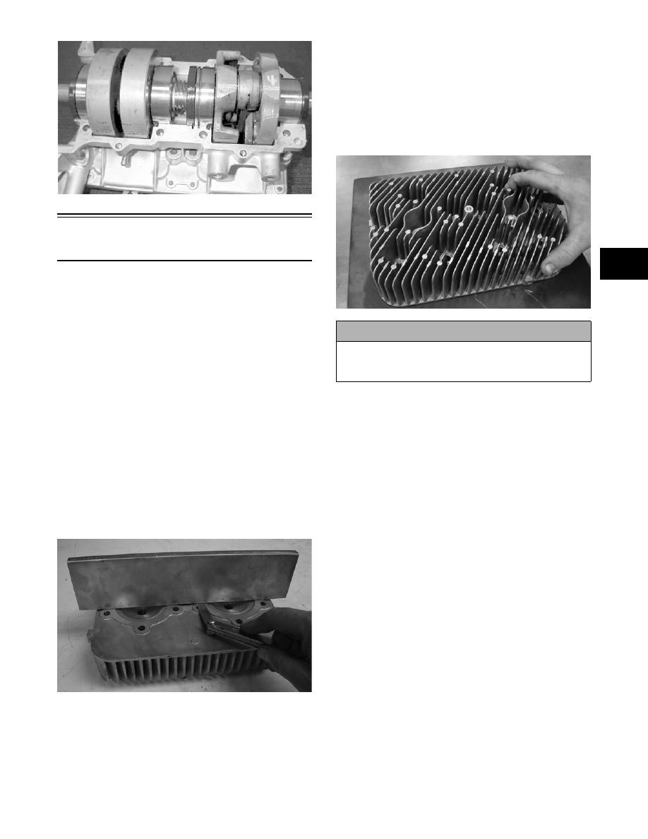
4. Place the cylinder head on a Surface Plate covered

with #400 grit wet-or-dry sandpaper. Using light

pressure, move each cylinder head in a figure eight

motion. Inspect the sealing surface for any indica-

tion of high spots. A high spot can be noted by a

bright metallic finish. Correct any high spots

before assembly by continuing to move the cylin-

der head in a figure eight motion until a uniform

bright metallic finish is attained.

MD2492

CYLINDERS

1. Using a non-metallic carbon removal tool, remove

carbon buildup from the exhaust ports.

2. Wash the cylinders in parts-cleaning solvent.

3. Inspect the cylinders for pitting, scoring, scuffing,

and corrosion. If marks are found, repair the sur-

face with Ball Hone and honing oil.

„NOTE: To produce the proper 45° crosshatch
pattern, maintain a low drill RPM. If honing oil is
not available, use a lightweight, petroleum-based
oil. Thoroughly clean the cylinders after honing
using detergent soap and hot water and dry with
compressed air; then immediately apply oil to the
cylinder bores. If a bore is severely damaged or
gouged, the cylinder will have to be replaced.

! CAUTION

Water or parts-cleaning solvent must be used in
conjunction with the wet-or-dry sandpaper or dam-
age to the sealing surface may result.

2-26

4. Place the head surface of each cylinder on the sur-

face plate covered with #400 grit wet-or-dry sand-

paper. Using light pressure, move each cylinder in

a figure eight motion. Inspect the surface for any

indication of high spots. A high spot can be noted

by a bright metallic finish. Correct any high spots

before assembly by continuing to move the cylin-

der in a figure eight motion until a uniform bright

metallic finish is attained.

PISTON ASSEMBLY

1. Using a non-metallic carbon removal tool, remove

the carbon buildup from the dome of each piston.

2. Take an old piston ring and snap it into two pieces;

then grind the end of the old ring to a 45° angle

and to a sharp edge. Using the sharpened ring as a

tool, clean carbon from the ring-grooves. Be sure

to position the ring with its tapered side up.

3. Inspect each piston for cracks in the piston pin and

skirt areas.

4. Inspect each piston for seizure marks or scuffing.

Repair with #400 grit wet-or-dry sandpaper and

water or honing oil.

AN135

„NOTE: If scuffing or seizure marks are too deep
to correct with the sandpaper, it will be necessary
to replace the piston.

5. Inspect the perimeter of each piston for signs of

excessive “blowby.” Excessive “blowby” indicates

worn piston rings or an out-of-round cylinder.

„NOTE: If synthetic oil is bing used, a certain
amount of “blowby” may be visible under normal
use.

CRANKCASE

1. Wash the crankcase halves in parts-cleaning sol-

vent.

„NOTE: Before washing the crankcase halves,
make sure the four bearing dowel pins have been
removed and accounted for.

2. Inspect the crankcase halves for scoring, pitting,

scuffing, or any imperfections in the casting.

3. Inspect all threaded areas for damaged or stripped

threads.

4. Inspect the bearing areas for cracks or excessive

bearing movement. If evidence of excessive bear-

ing movement is noted, the crankcase must be

replaced.

5. Inspect the bearing dowel pins for wear.

6. Inspect the sealing surfaces of the crankcase

halves for trueness by placing each crankcase half

on the surface plate covered with #400 grit wet-or-

dry sandpaper. Using light pressure, move each

half in a figure eight motion. Inspect the sealing

surfaces for any indication of high spots. A high

spot can be noted by a bright metallic finish. Cor-

rect any high spots by continuing to move the half

in a figure eight motion until a uniform bright

metallic finish is attained.

„NOTE: Care must be taken not to remove an
excessive amount of aluminum, or the crankcase
will have to be replaced. If excessive aluminum is
removed, too much pre-load will be exerted on the
crankshaft bearings when assembled.

MD0200A

ADAPTER PLATES

1. Inspect for cracks, scoring, pitting, imperfections,

or warping.

! CAUTION

Water or parts-cleaning solvent must be used in
conjunction with the wet-or-dry sandpaper or dam-
age to the sealing surface may result.

! CAUTION

Improper cleaning of the ring-grooves by the use of
the wrong type of ring-groove cleaner will result in
severe damage to the piston.

! CAUTION

Water or parts-cleaning solvent must be used in
conjunction with the wet-or-dry sandpaper or dam-
age to the sealing surface may result.

2-27

2

2. Inspect the sealing surfaces for trueness by placing

each on the surface plate covered with #400 grit

wet-or-dry sandpaper. Using light pressure, move

both sides in a figure eight motion. Inspect the

sealing surface for any indication of high spots or

warping. Correct high spots by continuing to move

each side in a figure eight motion. Warped compo-

nents must be replaced.

„NOTE: In order to inspect adapter plate trueness,
it will be necessary to remove the studs.

A932

CRANKSHAFT

„NOTE: If any servicing of the connecting rods,
center bearings, or oil-injection pump drive gear is
necessary, Arctic Cat recommends that the crank-
shaft be taken to a qualified machine shop for that
service.

1. Wash the crankshaft with bearings in parts-clean-

ing solvent.

2. Inspect the bearings for wear, scoring, scuffing,

damage, or discoloration. Rotate the bearings.

Bearings must rotate freely and must not bind or

feel rough. If any abnormal condition is noted,

replace the bearing.

FC039

3. Inspect the connecting-rod bearings by rotating

them. The bearings must rotate freely and must not

bind or feel rough. If a connecting-rod bearing

must be replaced, the connecting rod and crank pin

must also be replaced.

FC040

4. Inspect the oil-injection pump drive gear for any

signs of worn or chipped teeth. If either condition

exists, replace the gear.

„NOTE: Lubricate bearings thoroughly prior to
assembly.

REMOVING OUTER 
CRANKSHAFT BEARINGS

„NOTE: Steps 1-2 are for removing the MAG-side
bearing.

1. Place the crankshaft in a suitable support; then

install Crankshaft Bearing Remover between the

journal and the MAG-side bearing.

2. Place the protective cap on the crankshaft end;

then remove the bearing from the end of the crank-

shaft. Account for any shim(s).

AN068D

„NOTE: For installing purposes, note the offset
position of the dowel pin hole.

3. The PTO-side bearing may be removed simply by

sliding the bearing off the PTO end.

! CAUTION

Water or parts-cleaning solvent must be used in
conjunction with the wet-or-dry sandpaper or dam-
age to the sealing surfaces may result.

2-28

AN151A

4. Inspect the crankshaft bearing area for wear. If any

wear is noted on either end, replace the crankshaft

end.

INSTALLING OUTER
CRANKSHAFT BEARINGS

„NOTE: On certain models, steps 1-3 are for
installing the MAG-side bearing.

1. Secure the crankshaft vertically in a suitable fix-

ture or clamping device.

2. Heat the bearing either by placing the entire bear-

ing in a pan of oil on a hot plate or by squirting oil

into the bearing and using a propane torch to heat

the inner race of the bearing until a slight smoke is

noted coming from the bearing.

3. Place any shims removed during disassembly onto

the crankshaft; then slide the bearing onto the

crankshaft making sure the dowel-pin hole in the

outer race is properly positioned and will align

with its hole and pin in the crankcase.

4. Slide the PTO-side bearing onto the PTO end mak-

ing sure the dowel-pin hole will align with the hole

and pin in the crankcase.

AN151A

REED VALVE ASSEMBLY

1. Inspect the reed valves, stoppers, and valve blocks

for cracks or any deterioration.

AQ046

2. Wash the reed valves, stopper, and cage assembly

in parts-cleaning solvent and blow dry.

3. Inspect the reed stopper height. Using a caliper,

measure the distance from the seat to the bottom

outer tip edge of the stopper. Measurement must

not exceed specifications. If measurement is not

within specifications, either bend or replace the

reed stopper.

AJ156

4. Inspect the reed-to-seat clearance. Using a feeler

gauge, measure the clearance. Clearance must be

less than 0.20 mm (0.008 in.). If clearance is not

within specifications, replace the reed valve.

5. To assemble, place the reed valves on the cage

with its clipped corner positioned to the lower

right hand corner of the cage. Place the reed stop-

per assembly into position and secure with the

three screws coated with red Loctite #271.

! CAUTION

DO NOT overheat the bearing.


Content   ..  20  21  22  23   ..