Snowmobile Arctic Cat (2008 year). Manual - part 23


  Index      Snowmobiles / ATV     Snowmobile Arctic Cat - service manual 2008 year


Search            


Content   ..  21  22  23  24   ..


Snowmobile Arctic Cat (2008 year). Manual - part 23


2-29

2

AQ047

Measuring Critical 

Components

CYLINDER HEAD VOLUME 

(Squish-Gap Method)

To check the squish gap, a micrometer and two heavy

pieces of solder will be needed.

1. Remove the spark plugs from the engine.

2. Simultaneously insert two pieces of solder down

through the spark plug hole and push them up

against the inner cylinder bore towards the MAG-

side and PTO-side of the cylinder.

3. Pull the recoil rope and crank the engine over sev-

eral times while the solder is being held firmly in

place.

4. Remove both pieces of solder from the cylinder.

Using the micrometer, measure the very end of the

squeezed solder piece. Record the reading.

„NOTE: If the solder hasn’t been squeezed by the
piston, a larger piece of solder must be used.
Repeat procedure.

5. Using the opposite end of the solder pieces, insert

them down through the spark plug hole towards

the PTO-side and MAG-side of the cylinder. Push

on the solder until they contact the inner cylinder

bore.

6. Pull the recoil rope and crank the engine over sev-

eral times. Remove both pieces of solder from the

cylinder and measure the opposite squeezed ends

with a micrometer. Record reading.

„NOTE: Measure from PTO to MAG-side of the pis-
ton to accurately measure the squish gap. Never
measure across piston, exhaust to carburetor
side, as the piston will rock and the reading won’t
be accurate.

Readings may vary from side to side. 

„NOTE: Make sure the smaller reading is 1.69 mm
(0.066 in.) or less.
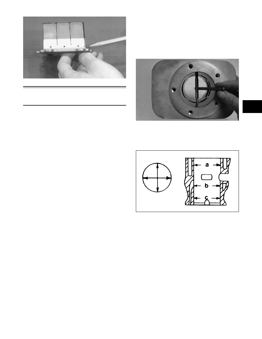
CYLINDER TRUENESS

1. Measure each cylinder in the three locations from

front to back and side to side for a total of six read-

ings.

MD2493

2. The trueness (out-of-roundness) is the difference

between the highest and lowest reading. Maxi-

mum trueness (out-of-roundness) must not exceed

0.1 mm (0.004 in.).

0725-586

PISTON SKIRT/CYLINDER 

CLEARANCE

1. Measure each cylinder front to back about 2.5 cm

(1 in.) from the bottom of each cylinder.

2. Measure the corresponding piston skirt diameter at a

point 1 cm above the piston skirt at a right angle to

the piston-pin bore. Subtract this measurement from

the measurement in step 1. The difference (clear-

ance) must be within 0.085-0.115 mm (0.0035-

0.0045 in.).

2-30

AC091

PISTON-RING END GAP

1. Place each piston ring in the wear portion above

the exhaust port of its respective cylinder. Use the

piston to position each ring squarely in each cylin-

der.

2. Using a feeler gauge, measure each piston-ring

end gap. Acceptable ring end gap must be within

0.030-0.050 mm (0.012-0.196 in.).

MD2501

PISTON PIN AND PISTON-PIN BORE

1. Measure the piston pin diameter at each end and in

the center. Acceptable piston pin measurement

must be within 17.995-18.000 mm (0.7085-0.7087

in.). If any measurement varies by more than

0.02 mm (0.001 in.), the piston pin and bearing

must be replaced as a set.

AN056

2. Insert a snap gauge into each piston-pin bore; then

remove the gauge and measure it with a microme-

ter. The diameter measurement must be within

18.002-18.010 mm (0.7087-0.7090 in.). Take two

measurements to ensure accuracy.

AC092

CONNECTING-ROD SMALL END 
BORE

1. Insert a snap gauge into each connecting-rod small

end bore; then remove the gauge and measure it

with a micrometer.

AN061

2. The diameter measurement must be within

23.003-23.011 mm (0.9056-0.9059 in.).

CRANKSHAFT RUNOUT

0742-727

1. Using the V Blocks, support the crankshaft on the

surface plate.

2-31

2

„NOTE: The V blocks should support the crank-
shaft on the outer bearings.

2. Mount a dial indicator and base on the surface

plate. Position the indicator contact point against

the crankshaft location point A (PTO-end) from

the crankshaft end. Zero the indicator and rotate

the crankshaft slowly. Note the amount of crank-

shaft runout (total indicator reading).

„NOTE: For runout location point specifications,
see Crankshaft Runout Specifications in Section 1
of this manual.

3. Position the indicator contact point against the

crankshaft location point B (MAG-end) from the

crankshaft end. Zero the indicator and rotate the

crankshaft slowly. Note the amount of crankshaft

runout (total indicator reading).

FC046

4. Position the indicator contact point against the

crankshaft at location point C (center). Zero the

indicator and rotate the crankshaft slowly. Note

the amount of crankshaft runout (total indicator

reading).

5. If runout exceeds 0.05 mm (0.002 in.) at any of the

checkpoints, the crankshaft must be either

straightened or replaced.

Assembling Engine


„NOTE: The use of new gaskets and seals is rec-
ommended when assembling the engine.

„NOTE: Before the engine is assembled, clean the
threads of the cap screws and the threaded areas
of the engine where Loctite will be used.

„NOTE: When the use of a lubricant is indicated,
use Arctic Cat 50:1 Injection Oil.

 1. Place the upper crankcase half (with its bottom

side up) on two blocks of wood.

2. Lightly grease the inner lips of the crankshaft

seals; then slide them onto the crankshaft.

3. Apply oil to the crankshaft bearings; then install

the crankshaft into the upper crankcase half. Be

sure the alignment hole in each bearing is posi-

tioned over its respective dowel pin in the crank-

case; then seat the crankshaft.

„NOTE: To check the bearing for proper position,
place the point of a sharp tool into the dimple
found in the bearing race. Strike the tool with the
palm of the hand in either direction. If the bearing
moves, it isn’t positioned correctly and must be
rotated until it drops onto the dowel pin. 

„NOTE: Make sure the crankshaft center C-ring
(integral with the center seal) is properly posi-
tioned in the groove of the upper crankcase half.

4. Install the four crankcase dowel pins.

5. Evenly apply a thin coat of Three Bond Sealant to the

entire bottom half crankcase sealing surface. 

„NOTE: Use only Three Bond Sealant to seal the
crankcase halves.

 MD0203

6. Install crankcase lower half. Install eight 8 mm

and four 6 mm cap screws. Tighten in three steps

the 8 mm cap screws to 17 ft-lb and the 6 mm cap

screws to 8 ft-lb using the pattern shown.

! CAUTION

To prevent damage to the crankshaft, crankshaft
bearings, or seals, make sure to always lift the
crankshaft from both ends.

! CAUTION

If the bearings are not properly seated during
assembly, the crankcase halves will not seal tightly
and severe engine damage will result.

2-32

737-027A

MD0212

„NOTE: Check the reed valve on each cylinder for
cracking or fraying around the edges. Make sure
they are closing completely.

„NOTE: To inspect a reed valve assembly, remove
the two Phillips-head screws securing the reed
valve and reed valve stopper to the block; then
remove the reed valve and stopper.

MD0088

„NOTE: Apply blue Loctite #243 on the Phillips-
head screws when assembling.

„NOTE: Make sure the angled corner on the reed
valve align with the angled corner on the reed
valve stopper.

MD0213

7.  Install the piston rings on each piston so the letter

on the top (inclined surface) of each ring faces the

dome of the piston.

726-306A

„NOTE: If the existing rings will not be replaced
with new rings, note the location and top side of
each ring for proper installation. When replacing
with new rings, replace as a complete set only.
When replacing rings note notches in ring ends
which correspond with locating pins in ring
grooves on intake side of the piston. This prevents
the rings from turning on the piston when assem-
bled.

! CAUTION

Do not over-tighten the Phillips-head screws when
installing the reed valves and reed valve stoppers.

! CAUTION

Incorrect installation of the piston rings will result in
engine damage.


Content   ..  21  22  23  24   ..