Snowmobile Arctic Cat (2008 year). Manual - part 20


  Index      Snowmobiles / ATV     Snowmobile Arctic Cat - service manual 2008 year


Search            


Content   ..  18  19  20  21   ..


Snowmobile Arctic Cat (2008 year). Manual - part 20


2-17

2

„NOTE: Apply a coat of Anti-Seize Thread Com-
pound to the keyway end of the driven shaft.

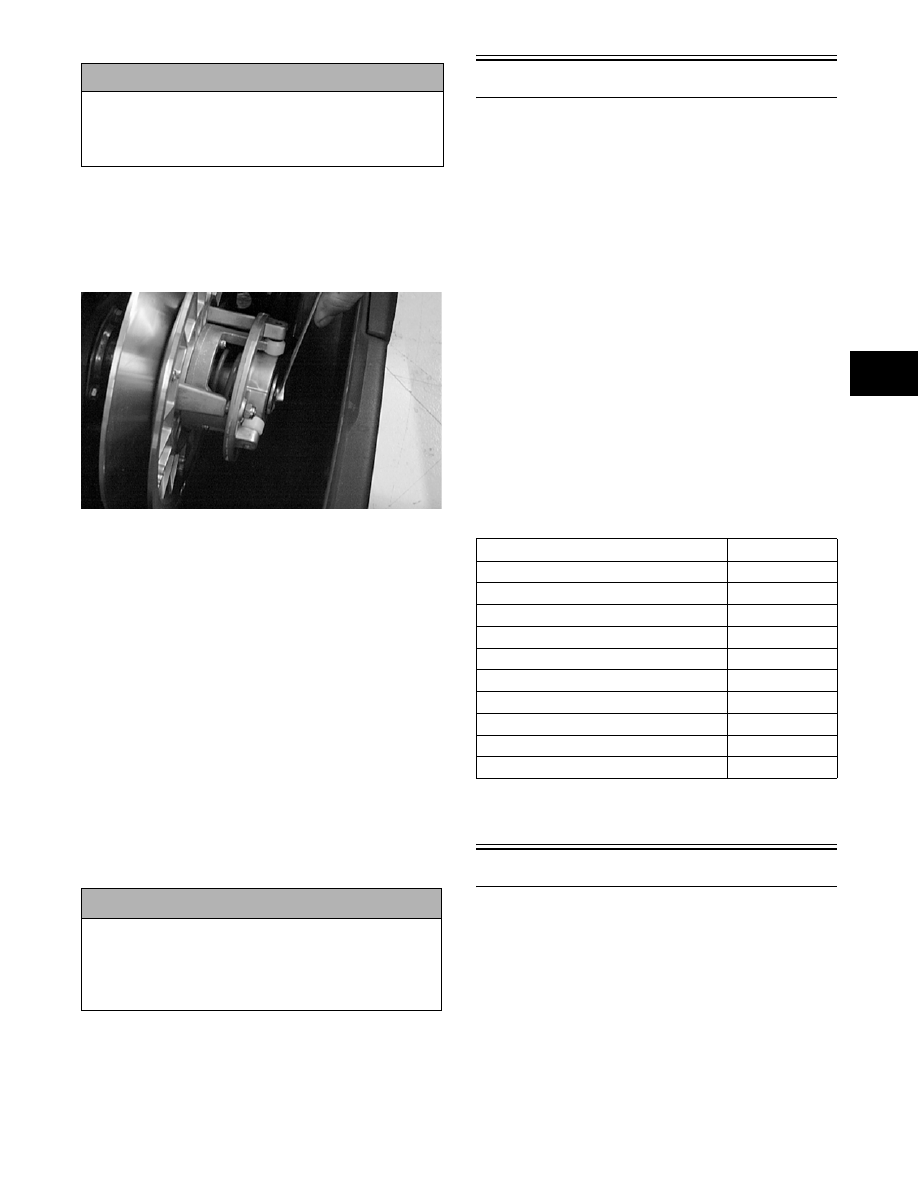
11. Install the driven pulley and alignment washers.

Secure with a cap screw (threads coated with blue

Loctite #243) and washer tightened to 24 ft-lb.

SC013D

„NOTE: At this point, check drive clutch/driven
pulley alignment (see Section 6).

12. Install the drive belt and secure the belt guard.

Install the plug in the belly pan.

„NOTE: If equipped with electric start, connect the
battery.

13. Turn the gas tank shut-off valve to the OPEN posi-

tion.

14. Check the ignition timing.

15. Place the rear of the snowmobile up on a shielded

safety stand. Start engine and allow to warm up.

Adjust engine idle to 1500 RPM and check all

safety switches for proper operation.

16. Test drive the snowmobile; then verify the tighten-

ing torque of the drive clutch.

Engine - Bearcat 570

This engine servicing sub-section has been organized

to show a progression for the complete servicing of the

Arctic Cat 570 cc (Bearcat 570) engine. For consis-

tency purposes, this sub-section shows a complete and

thorough progression; however, for efficiency it may

be preferable to remove the engine as a complete

assembly, to remove and disassemble only those com-

ponents which need to be addressed, and to service

only those components. Also, some components may

vary from model to model. The technician should use

discretion and sound judgment.

„NOTE: Critical torque specifications can be
found in Section 1 of this manual.

„NOTE: Some illustrations and photographs used
in this section are used for clarity purposes only
and are not designed to depict actual conditions.

SPECIAL TOOLS

A number of special tools must be available to the

technician when performing service procedures in this

engine section.

„NOTE: Special tools are available from the Arctic
Cat Service Parts Department.

Table of Contents

Removing .............................................................. 2-18
Disassembling ....................................................... 2-19
Cleaning and Inspecting........................................ 2-25
Measuring Critical Components ............................ 2-29
Assembling............................................................ 2-31
Installing ................................................................ 2-38

! CAUTION

When installing the drive clutch, do not tighten the
clutch bolt with any kind of impact tool. Tighten bolt
using a hand torque wrench only. Failure to do so
could result in stationary sheave damage.

! CAUTION

If the engine had a major overhaul or if any major
component was replaced, proper engine break-in
procedures must be followed (see Section 1). If the
proper engine break-in procedures are not followed,
severe engine damage may result.

Description

p/n

Ball Hone

0644-292

Crankshaft Bearing Remover

0144-302

Drive Clutch Puller

0644-207

Drive Clutch Spanner Wrench

0644-136

Driven Pulley Puller

0744-023

Flywheel Spanner Wrench

0144-007

Flywheel Puller

0744-040

Piston Pin Puller

0644-328

Surface Plate

0644-016

V Blocks

0644-022

2-18

Removing Engine

„NOTE: If equipped with electric start, disconnect
the battery.

1. Turn the gas tank shut-off valve to the CLOSED

position.

2. Open the belt guard.

3. Remove the drive belt; then remove the plug from

the belly pan.

„NOTE: Before installing the clutch puller, apply
oil to the threads of the puller and a small amount
of grease to the tip of the puller.

4. Remove the bolt and lock washer securing the

drive clutch to the crankshaft; then using the Drive

Clutch Puller and an impact wrench or a breaker

bar and Drive Clutch Spanner Wrench, tighten the

puller. If the drive clutch will not release, sharply

strike the head of the puller with a hammer. Repeat

this procedure until the clutch releases.

CM006

CM007

5. Remove the clutch from the engine compartment.

6. Remove the cap screw and washer securing the

driven pulley; then slide the pulley off the driven

shaft. Account for and note the position of any

alignment washers.

„NOTE: If the driven pulley will not slide off the
driven shaft, use the Driven Pulley Puller for
removal.

SC013D

7. Loosen the torque bumper from the engine mount.

MS367A

8. Remove the springs securing the expansion cham-

ber to the exhaust manifold and resonator; then

remove expansion chamber.

MS368

9. Remove the cap screws and lock washers securing

the recoil starter assembly; then remove the starter.

Leave it in the engine compartment.

2-19

2

AB082

10. Disconnect the main wiring harness connector and

the CDI unit wiring harness.

11. Disconnect the impulse hose from the crankcase.

12. Disconnect the spark plug caps.

13. Loosen the carburetor flange clamps. Remove the

carburetors from the intake flanges and carburetor

boots. Place the carburetors to the side in an

upright position.

„NOTE: If equipped with electric start, remove the
lock nut and washer securing the ground cable to
the starter motor and loosen the two Allen-head cap
screws securing the flex-drive to the starter motor;
then remove the cap screws securing the starter
motor to the chassis. Remove the starter motor.

MS369A

MS370A

14. Disconnect the oil-injection cable from the oil-

injection pump. Account for the E-clip and

washer; then disconnect the oil supply hoses from

the pump and plug the hose to prevent leakage.

AB081

15. Remove the cap screws securing the engine to the

chassis. Account for washers, cap screws, and lock

nuts.

570-ENG07A

16. Lift the engine out of the engine compartment.

17. Remove the cap screws, washers, and lock wash-

ers securing the engine mounting brackets to the

engine; then remove the brackets.

Disassembling Engine

1. Remove the exhaust manifold. Account for the

gaskets.

2. Remove the nuts, lock washers, and washers

securing the intake flange assembly. Account for

the gaskets, insulators, and the heat deflector.

3. Remove the five cap screws securing the front

(exhaust-side) shroud to the cylinder head.

Account for the special washers.

2-20

MD0276

„NOTE: Cap screws securing the front and rear
shrouds use special washers. Keep the special
mounting hardware with the shrouds for assem-
bling purposes.

MD0065

4. Remove the spark plug grommets.

MD0060

5. Using Spanner Wrench to hold the starter pulley,

remove the cap screw securing the flywheel to the

crankshaft. Account for the flat washer and the

lock washer.

MD0282

6. Using Spanner Wrench to hold the starter pulley,

remove the three cap screws securing the starter

pulley and fan to the flywheel.

MD0275

7. Using Flywheel Puller or suitable substitute,

remove the flywheel.

„NOTE: To ensure the cleanliness of the flywheel
magnets, place the flywheel (with the magnets fac-
ing upward) on a clean bench.

8. Remove the six cap screws securing the rear

(intake-side) shroud; then remove the shroud.

Account for the special washers.

! CAUTION

To prevent damage to the crankshaft, install a pro-
tective insert into the end of the crankshaft. The
puller must bottom on the insert and not on the
crankshaft. Also, do not thread puller bolts more
than five threads into the flywheel. Damage to the
stator coils may result.


Content   ..  18  19  20  21   ..