Snowmobile Polaris High Performance (2001 year). Manual - part 74
REAR SUSPENSION/TRACK/TRACTION
7.7
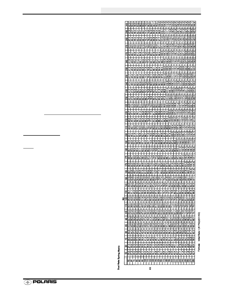
Dual Rate Springs
During initial compression of dual rate springs (two
separate springs stacked on top of each other, both
springs will compress resulting in an initial spring rate
that is a combination of both springs, yet less than ei-
ther of the individual springs. The chart at right shows
the inital combined spring rate using two individual
spring rates. The inital spring rate is based on the for-
mual below. For example, if you stack a 150 lb/in.
spring in combination with a 225 lb/in. spring, the chart
will give you an initial spring rate of 90 lb/in.
As the springs compress, there is a point where the
small spring compresses to solid, or the spring retain-
er contacts the transition spacers. This point is called
the transition point. Any compression of the springs
after this point is reached will result in a spring rate
equal to the spring rate of the long spring. This is true
because the smaller spring is no longer being com-
pressed.
Initial Rate=(Spring Rate #1) x (Spring Rate #2)
(Spring Rate #1) + (Spring Rate #2)
Example:
(150 lb/in) x (225 lb/in)=
(150 lb/in) + (225 lb/in)
33750=90 lb/in. inital spring rate
375
REAR SUSPENSION/TRACK/TRACTION