Snowmobile Polaris High Performance (2001 year). Manual - part 69


  Index      Snowmobiles / ATV     Snowmobile Polaris High Performance - service manual 2001 year


Search            


Content   ..  67  68  69  70   ..


Snowmobile Polaris High Performance (2001 year). Manual - part 69


STEERING / FRONT SUSPENSION

6.14

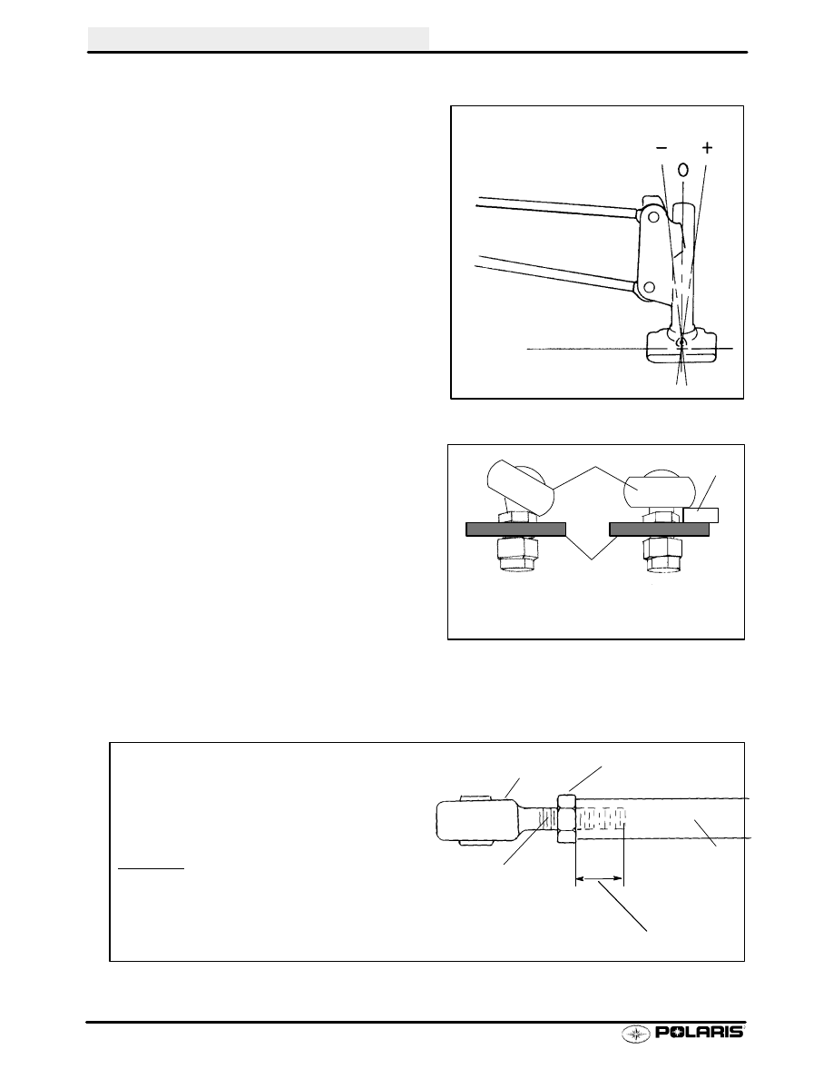
Camber Definition - All IFS

The following definitions of camber use automotive
terminology to describe positive and negative posi-
tions. Refer to the illustration at right.

S

0 (Neutral) Camber - Spindle is 90

(perpendicu-

lar) to ground

S

+ (Positive) Camber - Spindle bottom is canted
inward toward chassis

S

-- (Negative) Camber - Spindle bottom is canted

outward from chassis

Radius Rod and Tie Rod End Torque Procedure

Radius rod and tie rod ends must be parallel to their
respective mounting surface after tightening jam nut
as shown at right. Hold tie rod or radius rod and tigh-
ten jam nut. If possible, support the edge of the rod
end as shown to keep it from rotating out of position
until jam nut is tight. When tie rod ends are properly
tightened, the tie rod should rotate freely approxi-
mately 1/8 turn.

Rod End Engagement Guidelines - All IFS

Positive, Negative, and Neutral (0

) Camber

Front View

Incorrect

Correct

Tie Rod End

Mounting
Surface

Support
Edge

Tie Rod Or
Radius Rod

Thread Engagement

Tie Rod Or Radius Rod End

Tie Rod Or Radius Rod End Must
Engage Rod A Minimum Of 2x Thread
Diameter When Adjustment Is Complete

EXAMPLE
7/16

Rod End x 2 = 7/8

Minimum Thread Engagement =7/8

11mm x 2 = 22mm
Minimum Thread Engagement =22mm

Jam Nut

Diameter Of Rod
End x 2 = Minimum
Thread Engagement

STEERING / FRONT SUSPENSION

6.15

2001 IFS Steering Alignment Specifications

The following information is to be used for 2001 Polaris Snowmobile front suspension setup.
The data in the following table is based on the 2001 Polaris factory settings. Maximum Width
and Camber measurements are to be taken with the front end elevated and shocks at
full extension. Toe alignment is measured at ride height.

Suspension Type

Maximum Setup Width


1/4

(6mm)

Camber

Toe Out

(At Ride Height)

LITE IFS

40 3/16

(102.06 cm)

1/2

〉

1/2

340 Deluxe, 340 Touring

/

(

)

/

/

38

-Indy Xtra

Trail RMK

36 3/4

(93.35 cm)

0


1/2

38

-Xtra-10 CRC

500 RMK

37

(93.98 cm)

11/32

〉

1/2

38.2

XC-10 CRC

39 5

XC-10 CRC

37

(93.98 cm)

38 3/16

(100 cm)

5/8

〉

1/2

39.5

XC-10 CRC

600 RMK, 700 RMK, 800 RMK

38 3/16

(100 cm)

ALL MODELS

42.5” EDGE PRO X

(XCF SP, 440/600 Edge Pro X)

42 1/16”

1”


1/2

1/8

3/8

41

Indy Xtra

Sport Touring Sport Touring ES

39 1/8

(99.38 cm)

0


1/2

1/8

- 3/8

TOE OUT

Sport Touring, Sport Touring ES,

Sport Touring Euro

TOE OUT

42.5

Indy Xtra

40 7/16

(102.72 cm)

0


1/2

At Normal Ride

42.5 Indy Xtra

500 Classic, Classic Touring

40 7/16 (102.72 cm)

0


1/2

At Normal Ride

Height

42.5

X-10 CRC

40 7/16

(102.71 cm)

0


1/2

Height

42.5 X 10 CRC

600 Classic Touring

40 7/16 (102.71 cm)

0


1/2

42.5

XC-10 CRC

700 SKS 600 / 700 SKS Euro

40 3/4

(103.50 cm)

15/16

〉

3/4

700 SKS, 600 / 700 SKS Euro,

700 Classic, 800 XCR

42.5

EDGE

500 Indy, 500 / 600 / 700 / 800

XC, XC SP, Indy 500, Super-

sport, 600 Classic, 800 LE

40 1/2

(102.87 cm)

5/8

〉

1/2

WIDTH NOTE: Width is measured in inches from the center of the spindles near the grease fitting for the ski
mount bolt located at the base of the spindle. The tolerance on this measurement is


1/4

.

TOE ADJUSTMENT NOTE: Toe is measured in inches with the machine on the ground and resting at normal
ride height - not full rebound. Measure at a point 10

(254mm) forward of the ski mount bolt and 10

behind the

ski mount bolt, preferably on the centerline of carbide skags. Note: Measurements to points on the skis may be
inaccurate. See page 6.20.

NOTE: Camber measurement is taken in inches from top of alignment bar to the top of ski mount hole in the
spindle (bushing removed). See Page 6.18

STEERING / FRONT SUSPENSION

6.16

Prior to performing steering alignment, the suspension should be inspected for damage or wear and replacement
parts installed as required. See inspection on page 6.13.

WARNING

A maximum set up width is listed in the chart on page 6.15. Maximum set up width is the maximum allowable
distance between ski spindle centers with front end of vehicle off the ground and suspension fully extended. The
Maximum Set Up Width specifications are maximum width measurements, and are critical to ensure adequate
torsion bar engagement with the trailing arm. If the suspension is set too wide , the torsion bar may disengage
from trailing arm. 
Do not attempt to set the suspension wider than the specified Maximum Set Up Width.

Spindle Centering / Set Up Width / Camber Adjustment

1.

Make sure the track is properly aligned. Refer to Maintenance Chapter for procedure. This will be used as a
reference point for final toe out measurement.

2.

Support the front of the machine 1-2

(2.5-5.1 cm) with the skis off the floor.

3.

Remove skis and ski pivot bushings.

4.

Disconnect adjustable torsion bar linkage where applicable.

5.

Measure spindle to chassis centering as shown
and record measurement. Both spindles should be
an equal distance +/- 1/8

(3 mm) from the center of

the chassis after adjusting camber, width. This
measurement is controlled by adjusting radius rod
length.

6.

Measure

set

up

width

and

record.

This

measurement is controlled by adjusting radius rod
length, and must not exceed the Maximum Setup
Width listed in the appropriate table (at the front of
this section) after all steering adjustments are
complete. See illustration below for procedure.
NOTE: Camber / Width / and Centering are
dimentions that depend on each other. Each one
should be checked after any changes made.

Make marks here at the center of the contact
area. Measure from mark to mark

Measure the center to centerof the spindles with the front

end elevated and suspension fully extended to determine

set up width. Using a straight edge scribe a mark in the

center of the spindle. As close to the base of the spindle

tube as possible

Straight Edge

Spindle To Chassis

Centering

Left = Right


1/8

.

STEERING / FRONT SUSPENSION

6.17

Camber Adjustment

1.

Determine which spindle requires the greatest
amount of correction by installing the alignment
bar through one side to the opposite spindle.
Remove the bar and install it through the other
side to the opposite spindle. Measure from the
top of the bar to the top of the hole. Turn the upper
and lower radius rods (like a turn buckle) to
achieve the approperate camber width.
NOTE: Camber / Width / and Centering are
dimentions that depend on each other. Each one
should be checked after any changes.

2.

Using a 3/8

(1 cm) drive 11/16

(1.7 cm) crow foot

wrench and 20

(51 cm) long 3/8

(1 cm) drive

extension, loosen the radius rod end jam nut.
Remove the lower radius rod bolt from the spindle
requiring the most camber correction. Adjust the
opposite side next.

3.

To adjust camber, change lower radius rod length
until alignment bar measurement is within
specified range for each spindle. Refer to charts
on page 6.15 for camber specifications.

On

models with neutral camber (0) the bar should
slide freely through both spindles (


tolerance).

CAUTION:

Radius rod ends must remain parallel to the bulkhead
after rod end jam nuts are tightened to specified
torque. See illustration at right.

4.

Tighten all jam nuts. Torque radius rod attaching
bolts to specification.

WARNING

After camber adjustment is complete, be sure to measure set up width outlined on page 6.16 and compare to speci-
fications. Do not attempt to set suspension wider than the specified maximum set up width. If set up width exceeds
maximum, adjust upper and lower radius rods equally to maintain camber adjustment.

Measure Here

Remove
to Adjust

Rod End

Bulkhead

Rod end parallel to
mounting surface
when jam nut is tight.

Jam Nut

Radius Rod End Jam Nut Torque -

8-14 ft. lbs. (11-19 Nm)

Radius Rod Attaching Bolt Torque -

3/8

(outer) 28-30 ft. lbs. (38.6-41.4 Nm)

7/16

(inner top) 35-40 ft. lbs.

(48-55 Nm)

1/2

(inner bottom) 40-50 ft. lbs.

(55-69 Nm)


Content   ..  67  68  69  70   ..