Snowmobile Polaris High Performance (2001 year). Manual - part 49


  Index      Snowmobiles / ATV     Snowmobile Polaris High Performance - service manual 2001 year


Search            


Content   ..  47  48  49  50   ..


Snowmobile Polaris High Performance (2001 year). Manual - part 49


CLUTCHING

4.24

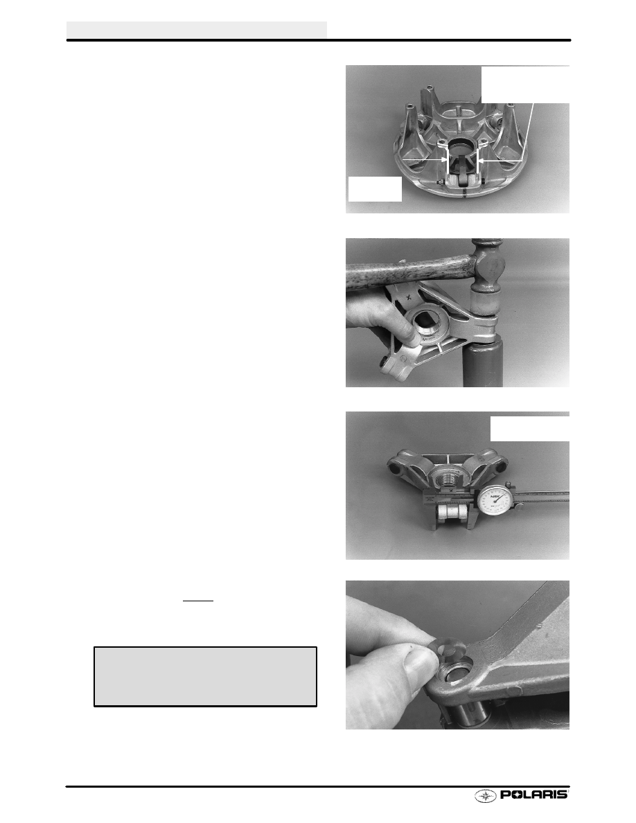
Spider Button Shimming, Cont.

2.

Measure the dimension between towers at the lower
half of the towers as shown.

3.

Install spider buttons using a soft face hammer.

4.

Record width of spider buttons on each leg.

5.

Add shims beneath trailing side spider button to
obtain specified button-to-tower clearance when
assembled.

Use Dial
Caliper

Measure tower
width at bottom
of travel

Measure each
leg and record

Button to Tower Clearance -

P-85 = .002

(.05 mm)

CLUTCHING

4.25

Drive Clutch Assembly

1.

Place the correct number of spacer washers
beneath the spider. Spacer PN 5132542 is a stepped
washer that cen be placed in addition to one of the
above shims for precise shimming.

2.

Assemble clutch making sure “X” marks on movable
sheave and spider, or reference marks made before
disassembly are aligned to achieve proper balance.

NOTE: If belt to sheave clearance is being changed by
adding or removing washers from under the spider, and
the sheaves were marked before disassembly, follow in-
dexing procedure on page 4.28.

3.

Torque spider to specification.

4.

Torque jam nut to specification (P-85 Clutches).
Install weights with weight pin nut on trailing side.
Use new nuts to ensure proper retention. Torque nut
to 30 in. lbs.

Marks

Spider Torque - P85 (all except 800 RMK)

Spider Removal Tool

PN 2872987

200 ft. lbs. (276 Nm)

Spider Torque - P85 (800 RMK)

Spider Removal Tool

PN 2872987

230-250 ft. lbs. (318-346 Nm)

Jam Nut Torque - P85 (except 800 RMK)

Jam Nut Tool

235 ft. lbs. (325 Nm)

PN 2870338

Weight Pin Nut Torque

30 In. Lbs. (3.4 Nm)

Jam Nut Torque - P85 (800 RMK)

200 ft. lbs. (277 Nm)

CLUTCHING

4.26

Assembly, Cont.

5.

Install spring and cover. Torque cover bolts evenly to
specification.

CAUTION:Carefully align bushing with shaft during
installation of cover to prevent bushing damage. Maintain
alignment by tightening cover bolts evenly and carefully.

Installation

1.

Slight galling or scoring of the bore taper can usually
be corrected using a tapered reamer. Place reamer in
a vise and lubricate with cutting oil. Clean taper by
manually rotating clutch clockwise.

2.

Check crankshaft taper for galling or scoring. If
necessary clean taper evenly with 200 grit emery
cloth.

3.

Both clutch taper and crankshaft taper should be
clean and dry.

NOTE: Do not use harsh cleaners which may cause
clutch taper to corrode during use. This will cause diffi-
culty when removing clutch in future. Clean clutch taper
with lacquer thinner or isopropyl alcohol.

Spider Cover Bolt Torque -

90 in. lbs. (10 Nm)

Tapered Reamer PN 2870576

CLUTCHING

4.27

Installation, Cont.

4.

Slide clutch fully onto crankshaft taper.

5.

Install retaining bolt with any spacers, washers or
O-rings. See appropriate parts manual for type and
placement of retaining bolt components.

6.

Torque retaining bolt to specifications. Hold clutch
with strap wrench.

NOTE: Re-torque clutch to specification after first peri-
od of operation (such as a test ride).

Drive Clutch Bolt Torque (14mm / 7/16

):

50 ft lbs. (69 Nm)


Content   ..  47  48  49  50   ..