Snowmobile Polaris High Performance (2001 year). Manual - part 27


  Index      Snowmobiles / ATV     Snowmobile Polaris High Performance - service manual 2001 year


Search            


Content   ..  25  26  27  28   ..


Snowmobile Polaris High Performance (2001 year). Manual - part 27


ENGINE

2.54

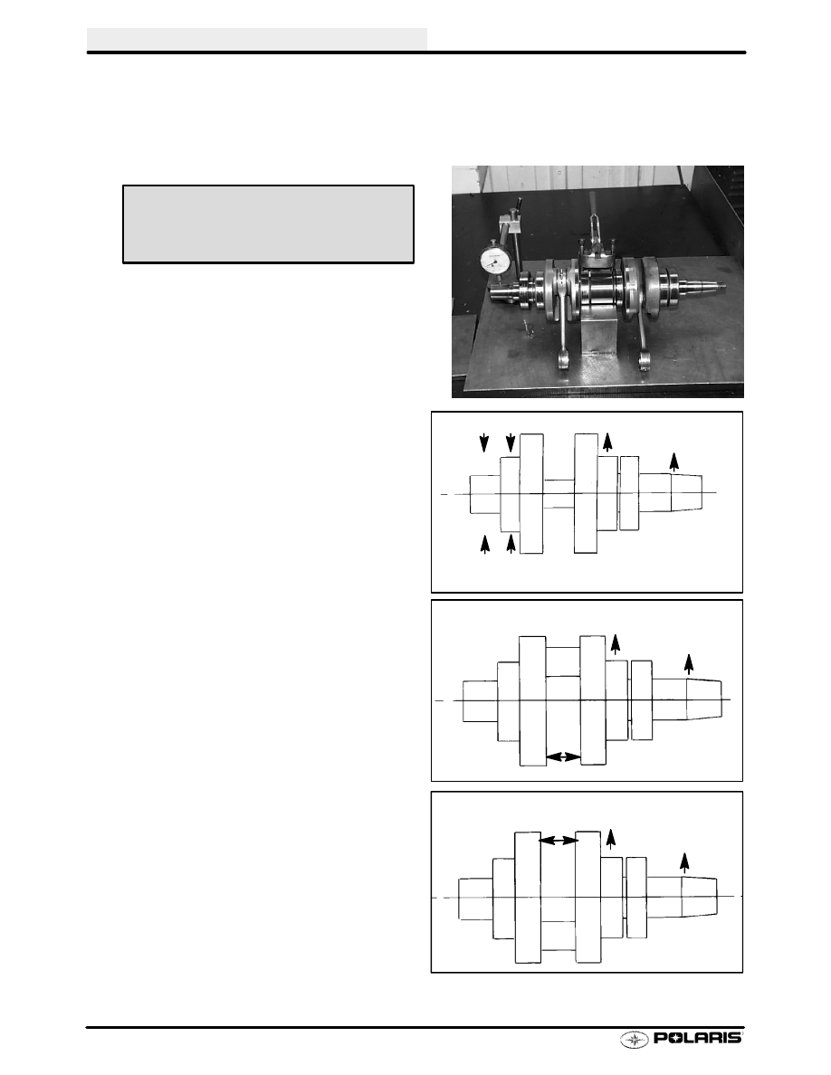
Crankshaft Straightening

Lubricate the bearings and clamp the crankshaft securely in the holding fixture. On three cylinder crankshafts,
straighten one of the ends (Magneto or PTO) and then straighten the center section. Place the center section
in the holding fixture and then straighten the remaining end. If truing the crankshaft requires striking with a
hammer, always be sure to re-check previously straightened areas to verify truing. Refer to the illustrations below.

NOTE: The rod pin position in relation to the dial indi-
cator position tells you what action is required to
straighten the shaft.

5.

To correct a situation like the one shown in the
illustration at right, strike the shaft at point A with a
brass hammer.

NOTE: The rod pin position in relation to the dial indi-
cator position tells you what action is required to
straighten the shaft.

6.

To correct a situation like the one shown in the
illustration at right, squeeze the crankshaft at
point A. (Use tool from alignment kit).

7.

If the crank rod pin location is 180

_

from the dial

indicator (opposite that shown above), it will be
necessary to spread the crankshaft at the A
position as shown in the illustration at right. When
rebuilding

and

straightening

a

crankshaft,

straightness is of utmost importance.

Runout

must be as close to zero as possible.

NOTE: Maximum allowable runout is .004

I

(.1 mm).

Crankshaft Alignment Fixture

PN 2870569

A

B

HIGH .004 (.1mm)

HIGH .004 (.1mm)

SUPPORT CRANKSHAFT
AT THESE TWO BEARINGS

A

A

HIGH .002 (.05mm)

HIGH .005 (.13mm)

A

HIGH .002 (.05mm)

HIGH .005 (.13mm)

A

ENGINE

2.55

Crankshaft Indexing

Polaris crankshafts are pressed together or ‘‘indexed” so
the connecting rod journal center lines are 180

(twins) or

120

(triples) apart from each other.

It is sometimes necessary to check multi-cylinder crank-
shafts to verify that one cylinder has not been forced out
of position relative to the other cylinder or cylinders.
Causes for out-of-index crankshafts include but are not
not limited to:

S

Hydrolock from water or fuel;

S

Impact to drive clutch from foreign object or acci-
dent;

S

Abrupt piston or other mechanical failure;

S

Engine lock-up due to drive belt failure;

Following is a method of checking:

CAUTION:

Disconnect battery ground cable and all spark plug high
tension leads; ground high tension leads to engine. Dis-
connect lanyard from engine stop switch before proceed-
ing with the following steps.

1.

Securely fasten a degree wheel on the flywheel or
PTO end of crankshaft. Use a large degree wheel for
more accuracy, and make sure it is mounted
concentrically with the crankshaft center line.

2.

Sharpen a coat hanger or section of welding rod and
anchor it to a convenient spot. Point the sharpened
end at the outer perimeter of the degree wheel.

3.

Install a dial indicator into the magneto end cylinder
spark plug hole (front) (#1). (The ignition timing is
referenced by the magneto end.)

4.

Rotate the engine to bring the piston to top dead
center (TDC) on the cylinder with the indicator
installed.

5.

Locate TDC as accurately as possible by finding the
center of the point where there is no piston
movement. ‘‘Zero” the dial indicator at this point.
Continue to rotate the crankshaft in the normal
direction of rotation until the dial indicator reads .100

(2.54mm) after top dead center (ATDC).

IMPORTANT: Do not allow the crankshaft to move
from this position.

Dial Indicator

Degree
Wheel

.100 ATDC

ENGINE

2.56

Crankshaft Indexing (Continued)

6.

Bend the pointer or move the degree wheel until the
pointer aligns with the 180

or 120

mark on the

degree wheel.

7.

With the pointer aligned, make sure the degree wheel
and pointer are secured and will not move out of
position.

Re-check accuracy of this location by

repeating steps 4. and 5. . The pointer should align
with the 180

or 120

mark when the dial indicator

reads .100

(2.54mm) ATDC.

IMPORTANT: Do not move the degree wheel or pointer
after the initial setting on the mag end cylinder - simply
read the wheel and dial indicator.

8.

Remove the dial indicator and install in cylinder #2 or
center cylinder. Repeat steps 4. and 5.

Note the

degree wheel indication when the dial indicator reads
.100

ATDC. It should be 180

or 120

(

2

) from

cylinder #1. Repeat procedure on PTO cylinder (#3)
where applicable. Cylinder #3 should also be 120


2

) from cylinder #1.

Symptoms of an out of index crankshaft can include:

S

Difficulty calibrating carburetor (repetitive plug
fouling on one cylinder with no other cause);

S

Unexplained piston failure on one cylinder (i.e.
severe detonation, broken ring lands, piston hol-
ing);

S

Excessive vibration of engine, backfiring, etc.;

S

Rough idle, poor top speed.

ENGINE

2.57

Cylinder Head Inspection

1.

Inspect each cylinder head for warping. Replace
cylinder head if warp exceeds service limit.

Cylinder Measurement

2.

Inspect each cylinder for wear, scratches, or
damage. If no damage is evident, measure the
cylinder for taper and out of round with a
telescoping gauge or a dial bore gauge. Measure
the bore 1/2

from the top of the cylinder; in line with

the piston pin and 90

to the pin to determine if the

bore is out of round. Repeat the measurements at
the middle and bottom of the cylinder to determine
taper or out of round at the bottom. Record all
measurements.

Cylinder Head Warp

Service Limit: .003

(.08mm)

Top

Middle

Bottom

X

X

X

Y

Y

Y

Cylinder Taper

Limit: .002 Max.

Cylinder Out of Round

Limit: .002 Max.


Content   ..  25  26  27  28   ..