Snowmobile Polaris High Performance (2001 year). Manual - part 25


  Index      Snowmobiles / ATV     Snowmobile Polaris High Performance - service manual 2001 year


Search            


Content   ..  23  24  25  26   ..


Snowmobile Polaris High Performance (2001 year). Manual - part 25


ENGINE

2.46

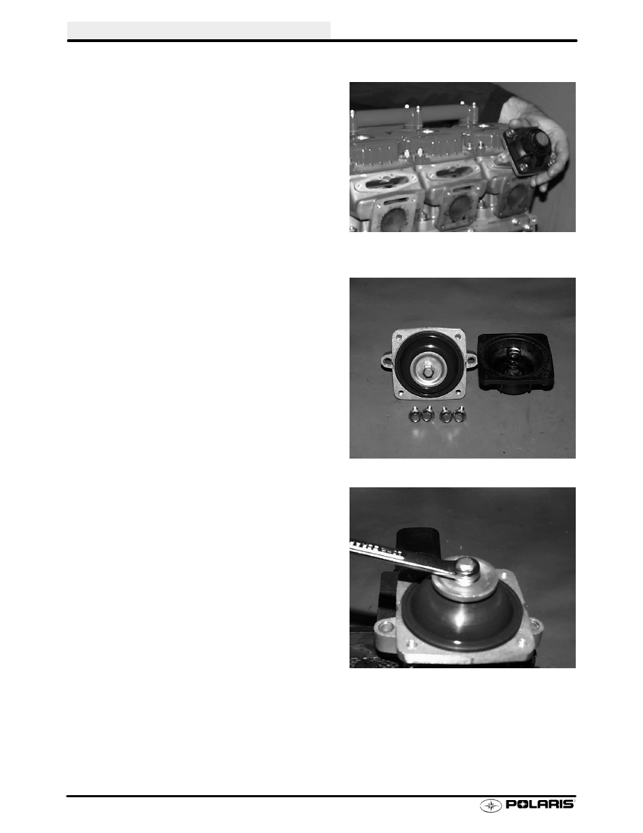
V.E.S. Removal - 800 XCR

1.

Remove two mounting bolts. Remove exhaust
valve assembly from cylinder.

2.

Remove four cover bolts, cover, and return
spring.

CAUTION:Valve is spring loaded. Hold cover in
position until all bolts are removed.

3.

If the spring stays in the cover, hold the cover
with spring facing toward you. Rotate spring in
a counterclockwise direction while pulling
outward on the spring. Do not distort the spring
upon removal.

4.

Insert V.E.S. in a soft jawed vice. Carefully
remove exhaust valve cap.

NOTE: Top nut is secured to valve with adhesive.
Removing top nut may damage threads on valve.

ENGINE

2.47

Disassembly, Cleaning, Inspection - VES

1. Clean O-ring and bellows in warm water and

mild detergent. Inspect bellows for holes, dis-
tortion or damage. Replace if necessary. In-
spect O-ring for damage.

2. Clean all other parts with solvent. Be sure all

parts are thoroughly clean.

3. Inspect the actuator port in cylinder and valve

housing. Be sure it is clear and not obstructed
by debris or carbon.

4. Carbon deposits can be removed from valve

with a Scotch Brite

t

pad or similar soft abra-

sive brush.

5. Lubricate exhaust valve with Polaris Premium

Gold 2-cycle engine lubricant. Install valve in
cylinder and move it through the entire travel
range to check for free movement without bind-
ing. If the valve sticks anywhere in the travel
range, check the valve and valve bore in the cyl-
inder for carbon deposits and clean if neces-
sary.

O-ring

Bellows

Clean with solvent

Clean with
Scotch Brite

t

or similar soft
abrasive brush

ENGINE

2.48

V.E.S. Assembly

1. Insert exhaust valve into valve housing. Re-

place housing gasket.

2. Install washer, beveled side out, and bellows.

3. Apply Loctite

t

262 to top 2 or 3 threads of valve

and install valve cap. Torque to specification.

4. Install spring, valve cover, and adjuster nut.

Torque exhaust valve cover bolts to specifica-
tion.

Valve Cap Torque:

6 Ft lbs (8.3 Nm)

Valve Cover Bolt Torque:

4 Ft lbs (5.5 Nm)

ENGINE

2.49

5. Install V.E.S. assembly onto cylinder and torque

V.E.S. housing bolts to specification. Set spring
adjuster screw to desired specification.

V.E.S. Adjustment

The RPM at which the exhaust valves open and
close can be tuned by turning the spring adjuster in
or out for the desired valve characteristics.

1.

Turning spring adjuster in:

S

Creates more spring pressure

S

Allows exhaust valve to open at slower rate

S

For applications such as drag racing

2.

Turning spring adjuster out:

S

Creates less spring pressure

S

Allows exhaust valve to open at faster rate

S

For applications such as trail riding

Riders can fine tune the VES to suit their riding con-
ditions and power delivery characteristics. Base
setting is with adjuster screw flush with housing.

CAUTION:Do not turn spring adjuster too far. The
spring adjuster is turned out to its maximum when
the adjuster is flush with top of housing.

V.E.S. Housing Bolt Torque:

9 Ft lbs (12.4 Nm)


Content   ..  23  24  25  26   ..