Snowmobile Polaris High Performance (2001 year). Manual - part 26


  Index      Snowmobiles / ATV     Snowmobile Polaris High Performance - service manual 2001 year


Search            


Content   ..  24  25  26  27   ..


Snowmobile Polaris High Performance (2001 year). Manual - part 26


ENGINE

2.50

Cylinder Service

Maximum engine performance and easy starting are directly related to the compression of the fuel and air mixture
in the combustion chamber. It is important that the cylinder walls are concentric, smooth and perpendicular to
the crankshaft center line. All new engines have these characteristics built into them, however, the stresses and
heat of operation may cause the bore to distort or score, resulting in loss of compression and power.

Inspection

A simple way of checking cylinder/piston condition is to remove the exhaust manifold and look into the exhaust
port. If there is a considerable amount of blow by (brown or black carbon deposit) under the piston rings, the
cylinder should be removed and honed. The piston rings should be replaced also.

The cylinder should always be inspected whenever an engine has been disassembled for repair or any time a
loss of power or cylinder cranking compression is noted. A visual inspection after the cylinder head is removed
will reveal if the cylinder should be removed for honing. Inspect for any scratches or signs of scoring or brown
areas which indicate ring leakage and distortion.
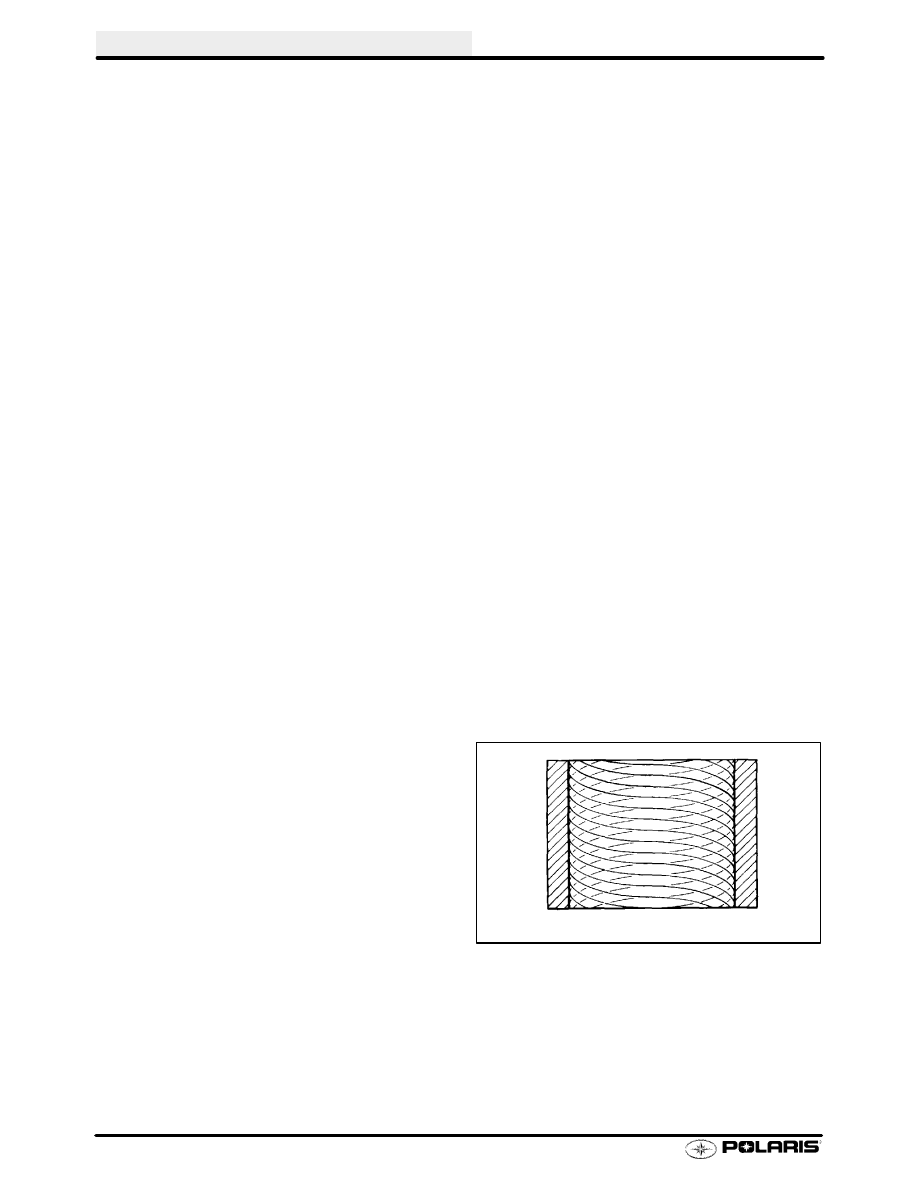
Cylinder Honing

The cylinder bore must be de-glazed whenever new piston rings are installed*. A light honing with fine stones
removes only a very small amount of material. A proper crosshatch pattern is important to provide a surface that
will hold oil, and allow rings to seat properly. If the crosshatch is too steep, oil retention will be reduced. A cross-
hatch angle which is too shallow will cause ring vibration, poor sealing, and overheating of the rings due to blow-by
and reduced contact with the cylinder wall. Service life of the pistons and rings will be greatly reduced.

* Except Nicasil

Cylinder Hone Selection

Selecting a hone which will straighten as well as remove material from the cylinder is very important. Honing a
cylinder with a spring loaded glaze breaker is never advised. Polaris recommends using a rigid type hone which
also has the capability of oversizing. These hones are manufactured by such companies as Sunnen Products
Company of St. Louis, Missouri; and Ammco Tools, Inc., of North Chicago, Illinois.

De-glazing

If cylinder wear or damage is minimal, hone the cylinder lightly with finish stones following the procedure outlined
on page 2.51

Honing To Oversize

If cylinder wear or damage is excessive, it will be nec-
essary to oversize the cylinder using a new oversize
piston and rings. This may be accomplished by either
boring the cylinder and then finish honing to the final
bore size, or by rough honing followed by finish honing.

For oversize honing always wet hone using honing oil
and a coarse roughing stone. Measure the piston (see
piston measurement) and rough hone to the size of the
piston or slightly larger. Always leave .002 - .003

(.05

- .07 mm) for finish honing. Refer to the Snowmobile
Service Manual for piston to cylinder specifications be-
fore honing. Complete the sizing with fine grit stones
to provide the proper cross-hatch finish and required
piston clearance. See procedure on page 2.51.

EXAMPLE OF CROSS HATCH PATTERN

ENGINE

2.51

Honing Procedure

1.

Wash cylinder with solvent.

Clamp cylinder

securely in a soft jawed vise by the exhaust port
studs.

2.

Place hone in cylinder and tighten stone adjusting
knob until stone contacts the cylinder walls (DO
NOT OVERTIGHTEN). Cylinders may be wet or
dry honed depending on the hone manufacturer’s
recommendations.

Wet honing removes more

material faster and leaves a more distinct pattern in
the bore. Using a 1/2

I

(13 mm) drill motor rotating

at a speed of 300-500 RPM, run the hone in and out
of the cylinder rapidly until cutting tension
decreases.

Remember to keep the hone drive

shaft centered to prevent edge loading and always
bring the stone approximately 1/2

I

(1.3 cm)

beyond the bore at the end of each stroke. Release
the hone at regular intervals to inspect bore size
and finish. Do not “drag” the hone out of the bore.

Honing Procedure - NiCaSil

Ni-Ca-Sil cylinders can be lightly honed if the proper
stone is used. Ammco #3955 honing stones (for use
with the Ammco 3950 cylinder hone) are suitable and
can be ordered through most automotive supply stores
or VST. See General Information chapter for tool order-
ing information.

Port Chamfering

Remove the sharp edges at the bottom and top of each
port whenever boring or honing is performed. Make
sure there are no sharp edges.

IMPORTANT:

Cleaning the Cylinder After Honing

It is very important that the cylinder be thoroughly
cleaned after honing to remove all grit material. Wash
the cylinder in a solvent, then in hot soapy water. Pay
close attention to areas where the cylinder sleeve
meets the aluminum casting (transfer port area). Use
electrical contact cleaner if necessary to clean these
areas. Rinse thoroughly, dry with compressed air, and
oil the bore immediately with Polaris Premium 2 Cycle
Lubricant.

ENGINE

2.52

Crankcase Inspection / Bearing Fit

Any time crankshaft bearing failure occurs and the case
is to be reused, Polaris recommends checking the bear-
ing fit into the case halves using the following procedure.

1.

With case halves cleaned, press a replacement
bearing into each of the main bearing journals to
determine a basic amount of press fit. NOTE: Do a
comparison check of all journals by manually
forcing the bearing into the bearing seats noting if
any are noticeably loose or tight.

Normal hand

installation

will

be

an

indication

of

the

recommended interference fit. If the bearing falls
out of the case when the case is inverted, the case
should be replaced.

Crankshaft Main Bearing Inspection

1.

Clean crankshaft thoroughly and oil main and
connecting rod bearings with Polaris Premium 2
engine oil. Carefully check each main bearing on
the shaft.

NOTE: Due to extremely close tolerances, the bearings
must be inspected visually, and by feel. Look for signs
of discoloration, scoring or galling. Turn the outer race
of each bearing. The bearings should turn smoothly and
quietly. The inner race of each bearing should fit tightly
on the crankshaft. The outer race should be firm with
minimal side to side movement and no detectable up
and down movement. Replace any loose or rough bear-
ings.

Crankcase Bearing Interference Fit:

C-3 - .0006

(.015mm) - Crush

C-4 - .001

(.025mm) - Crush

ENGINE

2.53

Connecting Rod (Big End) Bearing Inspection

1.

Measure connecting rod big end side clearance with
a feeler gauge. Clearance should be equal on all
rods (within .002

). Rotate rod on crankshaft and

check for rough spots. Check radial end play in rod
by supporting rod against one thrust washer and
alternately applying up and down pressure.
Replace bearing, pin, and thrust washers if side
clearance is excessive or if there is any up and down
movement detectable in the big end bearing.

NOTE: Specialized equipment and a sound knowledge
of crankshaft repair and straightening is required to per-
form crankshaft work safely and correctly. Crankshaft
repair should be performed by trained Polaris service
technicians in a properly equipped shop.

Piston Pin / Needle Bearing Inspection

1.

Clean needle bearing in solvent and dry with
compressed air.

2.

Inspect needle cage carefully for cracks or shiny
spots which indicate wear. Replace needle bearings
if worn or cracked, and always replace them if piston
damage has occurred.

3.

Visually inspect piston pin for damage, discoloration,
or wear. Run your fingernail along the length of the
pin and replace it if any rough spots, galling or wear is
detected.

Connecting Rod Small End Inspection

1.

Clean small end of connecting rod and inspect inner
bore with a magnifying glass. Look for any surface
irregularities including pitting, wear, or dents.

2.

Run your fingernail around the inside of the rod and
check for rough spots, galling, or wear.

3.

Oil and install needle bearing and pin in connecting
rod. Rotate pin slowly and check for rough spots or
any resistance to movement. Slide pin back and
forth through bearing while rotating and check for
rough spots.

4.

With pin and bearing centered in rod, twist ends back
and forth in all directions to check for excessive axial
play. Pull up and down evenly on both ends of pin to
check for radial play. Replace pin and bearing if there
is any resistance to rotation or excessive axial or
radial movement. If play or roughness is evident with
a new pin and bearing, replace the connecting rod.


Content   ..  24  25  26  27   ..