Snowmobile Polaris High Performance (2001 year). Manual - part 20


  Index      Snowmobiles / ATV     Snowmobile Polaris High Performance - service manual 2001 year


Search            


Content   ..  18  19  20  21   ..


Snowmobile Polaris High Performance (2001 year). Manual - part 20


ENGINE

2.26

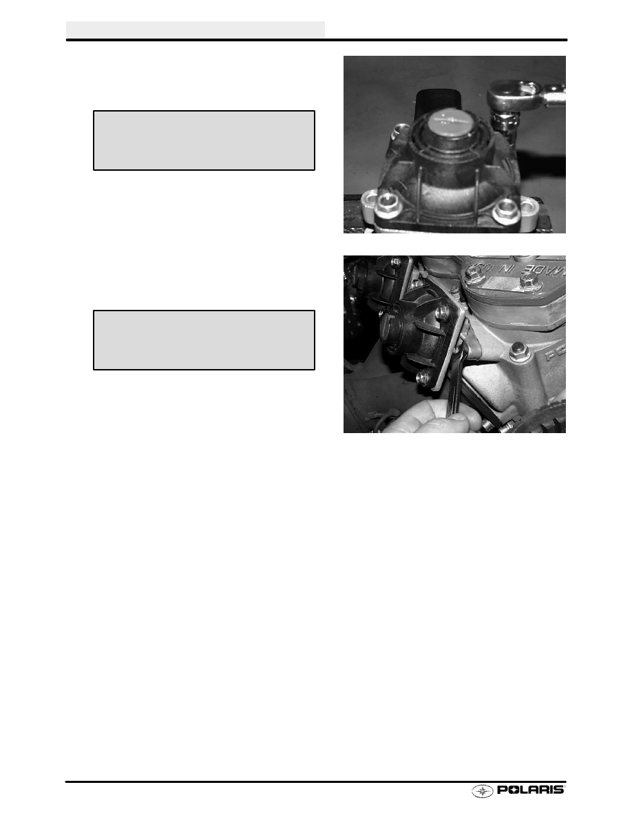
4. Install spring, valve cover, and adjuster nut.

Torque exhaust valve cover bolts to specifica-
tion.

5. Install V.E.S. assembly onto cylinder and torque

V.E.S. housing bolts to specification. Set spring
adjuster screw to desired specification.

V.E.S. Adjustment

The RPM at which the exhaust valves open and
close can be tuned by turning the spring adjuster in
or out for the desired valve characteristics.

1.

Turning spring adjuster in:

S

Creates more spring pressure

S

Allows exhaust valve to open at slower rate

S

For applications such as drag racing

2.

Turning spring adjuster out:

S

Creates less spring pressure

S

Allows exhaust valve to open at faster rate

S

For applications such as trail riding

Riders can fine tune the VES to suit their riding con-
ditions and power delivery characteristics. Base
setting is with adjuster screw flush with housing.

CAUTION:Do not turn spring adjuster too far. The
spring adjuster is turned out to its maximum when
the adjuster is flush with top of housing.

Valve Cover Bolt Torque:

4 Ft lbs (5.5 Nm)

V.E.S. Housing Bolt Torque:

9 Ft lbs (12.4 Nm)

ENGINE

2.27

NOTE: Inspect all parts for wear or damage during disassembly. Replace all seals, O-rings,
and gaskets with Genuine Polaris parts during assembly. Refer to pages 2.49-2.60 for gen-
eral inspection procedures.

Disassembly -- 600 big block, 700, 800 twins

1.

Remove oil pump.

2.

Remove recoil housing.

3.

Remove recoil hub. Inspect waterpump drive belt
for missing, cracked, or broken drive cogs. Replace
if worn.

Measure the belt at 4 different points as shown. Re-
place if width is less than .250

, (6.35mm). Nominal new

width is .345

, (8.75mm). Refer to page 2.68 for water

pump belt installation.

Replace if width is
less than .25

(6.35mm)

ENGINE

2.28

Disassembly, Cont.

4.

Remove drive gears and belt.

5.

Remove flywheel nut using flywheel holder.

6.

Remove flywheel using flywheel puller.

7.

Note the ignition timing strip on the flywheel.

8.

Before removing stator plate, mark the plate and
crankcase for reference upon assembly.

Flywheel Holder

PN 8700229

Flywheel Puller

PN 2871043

ENGINE

2.29

Disassembly, Cont.

9.

Remove bolts holding water pump housing to
crankcase.

Loosen hose clamp and remove

housing.

10. Inspect water pump weep hole for signs of leakage

or blockage.

11. Remove crankshaft seal from housing by driving

seal to inside of housing. Replace seal if removed.

12. Remove water pump cover bolts.

Hose Clamp

1

2

3

4

Inspect Weephole


Content   ..  18  19  20  21   ..