Snowmobile Polaris 2006 - 2007 FS / FST. Manual - part 45


  Index      Snowmobiles / ATV     Snowmobile Polaris 2006 - 2007 FS / FST - service manual


Search            


Content   ..  43  44  45  46   ..


Snowmobile Polaris 2006 - 2007 FS / FST. Manual - part 45


8.15

PVT System

8

Rev. 1 07/2006

Roller Removal

1.

With the spider in a vise start removing the spider buttons
by drilling a 0.18" hole in the center of a button on one side
of the spider.

2.

Place spider on a vise or in an arbor press.

3.

Place a pin punch through the spider button hole and drive
the opposite button and pin out.

4.

Remove shims (if any are installed) and note their location.

5.

Flip the spider over and tap out the holed button.

Roller Installation

NOTE:  CAUTION: Use care to start the pin straight.
Aluminum burrs could pass through into the roller
bushing causing it to bind and stick. Also use care
to make sure the roller remains aligned when the pin
is driven through. The roller busing could be
damaged causing premature wear and roller failure.

1.

Drive pin into the spider leg.100" -.125" (0.25 - 0.32cm)
beyond the first land of the spider leg.

2.

Install one washer on the portion of the pin that is
protruding from the spider leg.

3.

Install new buttons into the spider

4.

Place roller  in spider leg and center it on the pin.

5.

Place a second washer on the other side of the roller.

6.

Place the spider on a vise.

7.

Install pin centering tool (PN 2870401).

8.

Drive the roller pin through the second land of the spider.

9.

Repeat process for the other two rollers.

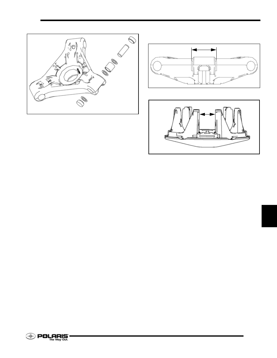
10. Measure the width of the spider leg with the buttons

installed (9) and record the measurement. Specification is
1.496" (37.99mm).

11. Measure the width of the moveable sheave towers.

Specification is 1.50" (38.1mm).

12. Subtract the spider measurement form the tower

measurement. The clearance between the spider buttons
and the moveable sheave towers is .002" - .004" (.05 -
.10mm).

SPIDER

BUTTON

SHIM

WASHER

ROLLER

ROLLER PIN

WASHER

8.16

PVT System

Rev. 1 07/2006

Clutch Assembly

1.

Assemble the rollers, bushings and roller pins if they were
removed.

2.

Install the head of the weight pin so that it is on the leading
side of rotation. This will orientate the nut on the trailing
side of rotation.

3.

Torque weight pin to 30 in-lb. (3Nm).

4.

Place the moveable sheave onto the stationary sheave.

5.

Place the same number of spacers on top of the stepped
spacer onto the shaft of the stationary sheave.

6.

Thread the spider onto the stationary sheave shaft.

7.

Index the spider. See “Spider Indexing” on page 8.17.

8.

Using the spider tool (PN 2870341) torque to 200 ft.-lb.
(276Nm).

9.

Install the jam nut (6) onto the shaft and torque it to 235 ft.-
lb. (324 Nm).

10. Place the drive spring on the shaft.

11. Place the cover onto the clutch and torque the cover

fasteners to 90 in-lb. (10Nm).

NOTE:  Do not allow side loading or mis-alignment of
the cover or the bushing may become damaged.

JAM NUT

SPACERS

CLUTCH SPACER

8.17

PVT System

8

Rev. 1 07/2006

Spider Indexing

NOTE: 

Spider indexing effects belt to sheave

clearance and clutch balance. Please read all
procedures before proceeding.

1.

Remove and disassemble clutch 

2.

Add or remove spider washers as required to achieve
desired belt to sheave clearance. Make sure that the stepped
washer (A) is on the bottom of the spacer stack (B). For
example: If belt to sheave clearance is .020

″ too large,

removing one .020

″ shim will position the movable sheave

closer to the fixed sheave reducing belt to sheave clearance
by .020

″.

3.

Place the correct number of spacer washers (B) beneath the
spider. The following washers are available for fine tuning:

• 5210752 - .020

″ (.51mm)

• 5242981 - .025

″ (.63mm)

• 5210753 - .032

″ (.81mm)

• 5210754 - .050

″ (1.27mm)

• Clutch Spacer - .130

″ (3.3mm)

4.

Install spider washer(s) and spider aligning the “X” with the
moveable sheave’s “X”. Notice as the spider seat location
is changed, the sheave marks made before disassembly no
longer align (C). There are two ways to bring the sheave
marks into alignment.

Vary the amount and thickness of spacer washers (washer
thickness may vary slightly). Re-index marked spider leg to
another tower. This can be done because spider has little effect
on overall clutch balance. 

Re-indexing the spider 1/3 turn clockwise, or 1 leg, will allow
the realignment of the moveable and stationary sheaves as
previously marked (D). For EXAMPLE: 0.020" or 0.032" (0.5
- 0.8mm) washer removed - re-index spider clockwise 1/3 turn.

NOTE: Alignment marks on the sheaves should be
with in 1" (25.4mm) after final assembly and
torquing.

(A)

(B)

8.18

PVT System

Rev. 1 07/2006

Drive Clutch Installation

NOTE: Always clean the clutch taper before re-
installing clutch on engine.

1.

Place a clutch taper reamer (PN 2870576) in a vise (A) and
lubricate the cutting edges with cutting oil. Clean the
clutch taper by manually rotating the clutch clockwise on
the reamer one or two revolutions. Only use the weight of
the clutch and do not push down on the clutch while
turning. This will clean up any galling or scoring of the
bore taper.

2.

Check crankshaft taper for galling or scoring. If necessary
clean the taper evenly with 200 grit emery cloth (B).

3.

The clutch taper and the crankshaft taper should be clean
and dry. Do not use harsh cleaners which may cause clutch
taper to corrode, or damage the crank seal.

4.

Clean clutch taper with lacquer thinner or isopropyl alcohol
(C).

5.

Slide clutch onto crankshaft taper (D).

6.

Install the retaining bolt with all spacers and washers or o-
rings (E) that were on the bolt when it was removed.

7.

Hold the clutch with the holding wrench (F) PN 931417-
A. Re-check torque after first operation or test ride.

8.

Torque retaining bolt to specification.

9.

Run engine then re-torque the retaining bolt to
specification.

Drive Clutch Bolt Torque

ENGINE

BOLT

TORQUE

FS / FST

14 mm

50 Ft.Lb.  (68Nm)

CAUTION

Re-torque the drive clutch bolt after running the engine 

for several minutes.


Content   ..  43  44  45  46   ..