Snowmobile Polaris 2006 - 2007 FS / FST. Manual - part 44


  Index      Snowmobiles / ATV     Snowmobile Polaris 2006 - 2007 FS / FST - service manual


Search            


Content   ..  42  43  44  45   ..


Snowmobile Polaris 2006 - 2007 FS / FST. Manual - part 44


8.11

PVT System

8

Rev. 1 07/2006

Drive Belts

*Belt dimensions are given in nominal dimensions. There is a +/
- variance for all critical dimensions. Clutch set up must be
inspected when a new belt is installed and, if necessary adjusted.

The drive belt is an important component of the converter
system. In order to achieve maximum efficiency from the
converter, drive belt tension (deflection), clutch offset, and
alignment must be adjusted properly.
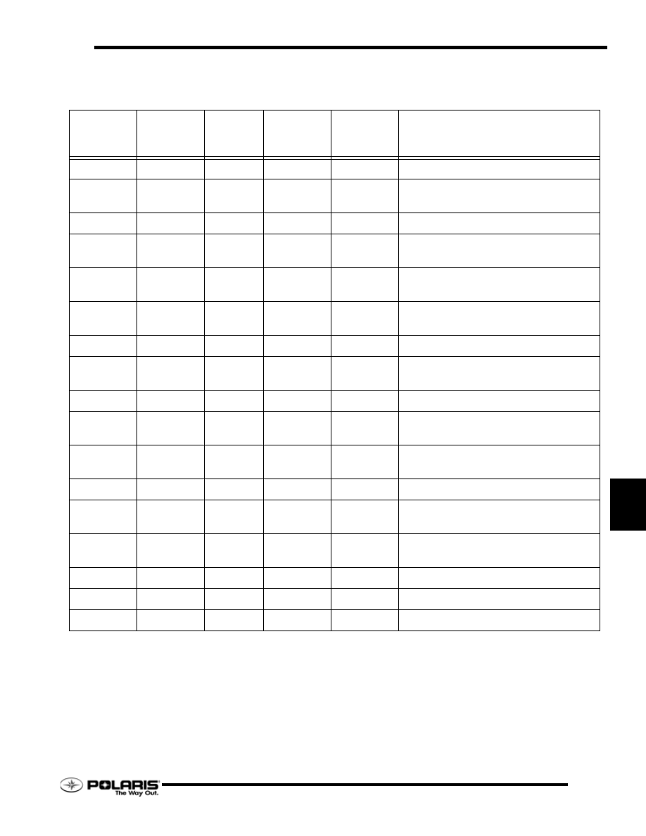
Part 

Number

Belt Width 

(Projected)*

in/mm

Side 

Angle 

Overall*

Center to 

Center in/

cm*

Outer 

Circumfere

nce in/cm

Notes

3211042

1.375/34.9

32_

12/30

47.25/120

Common production belt.

3211045

1.375/34.9

32_

12/30

47.125/

119.7

Close tolerance version of 3211042

3211058

1.250/31.75

28_

11/28

43.313/110

P-90 belt

3211059

1.250/31.75

28_

12/30

45.125/

114.6

Longer P-90 belt

3211061

1.375/34.9

32_

12/30

47.188/

119.9

CVT version of 3211045

3211065

1.438/36.5

28_

12.5/31.75

48.375/

122.9

CVT Double Cog Storm belt

3211066

1.375/34.9

28_

12/30

47.25/120

Double Cog-CVT- thicker than the 3211070.

3211067

1.375/34.9

28_

12/30

47.25/120

“Sticky compound” Good for low 
horsepower trail riding. Drag racing belt.

3211070

1.375 / 34.9

28_

12/30

47.25/120

Late model P-85 systems

3211073

1.438 / 36.5

28_

12.5/31.75

48.375/

122.9

“Sticky compound” Good for low 
horsepower trail riding. Drag racing belt.

3211074

1.438 / 36.5

28_

12/30

47.625/121

“Sticky compound” Good for low 
horsepower trail riding. Drag racing belt.

3211075

1.438 / 36.5

28_

12/30

47.625/121

Double Cog CVT

3211080

1.438 / 36.5

28_

11.5/29.2

46.625/

118.4

Double Cog CVT version of 3211078

3211078

1.438 / 36.5

28_

11.5/29.2

46.62 / 

118.4

Standard Drive Belt

3211099

1.490 / 37.84

28_

11 / 27.9

46.06 / 116.9

Double Cog CVT

3211111

1.537 / 39

28_

11.5/29.2

47.67 / 121

Super Cog Belt 

3211115

1.46 / 37.1

26_

11.5 / 29.2

46.77 / 118.8

MBL Drive Belt

8.12

PVT System

Rev. 1 07/2006

PVT SYSTEM ADJUSTMENTS

Clutch Alignment / Offset

The engine is mounted in the bulkhead so the drive and driven
clutches self-align under high torque loads.

Offset is controlled by the number of washers installed on the
jackshaft behind the driven clutch.

1.

Remove drive belt.

2.

Install the correct alignment tool depending on the type of
driven clutch installed on the snowmobile.

NOTE:  A standard alignment tool will not work with
a Team LW driven clutch. Likewise, a LW alignment
tool will not work with a standard Team driven
clutch. A Team LW driven clutch can be identified as
having 24 cooling fins.

3.

The optimum setup is when the front and rear of the tool
touch the driven clutch. No gap should be present in the
front, and the rear clearance should not exceed .060"
(3mm).

NOTE: If the front of the alignment bar does not
touch the driven sheave, the maximum clearance
cannot exceed .025

.

Offset Adjustment

1.

Determine direction driven clutch needs to be adjusted.

2.

Remove driven clutch retaining bolt, and remove driven
clutch.

3.

Add or remove washers from the jackshaft between the
driven clutch and jackshaft bearing to achieve proper offset.

4.

After adjusting offset, add or remove shim washers from
the retaining bolt to provide a +/- 0.030” (.75mm) of float
on the jackshaft.

T

OOL

 P

ART

 N

UMBER

A

PPLICATION

PS-46998

Standard Team Driven

PS-47477

Light Weight (LW) Team Driven

CAUTION

Always verify the driven clutch floats on the jackshaft 

after securing the fastener. The jackshaft bearing will fail 
due to side-loading if the driven clutch is not allowed to 

float.

0” - .060”

Touching

(PN: PS-46998 Shown)

8.13

PVT System

8

Rev. 1 07/2006

DRIVE CLUTCH

Identification

Every clutch will have the last three digits of the clutch part
number etched on to the cover (A). The “X" (B) marking is an
index mark where the clutch cover (C), clutch spider (D) and the
stationary sheave (E) should line up when the clutch is
assembled.

Drive Clutch Removal 

NOTE:  All clutch tools can be found at the 
beginning of this chapter. 

1.

Remove the belt..

2.

Place the clutch holding tool (PN 9314177-A) on the drive
clutch.

3.

Remove the drive clutch retaining bolt. Note the placement
and number of washers on retaining bolt.

4.

Insert the correct clutch puller into the retaining bolt hole.

5.

Tighten the puller into the clutch. If the clutch does not
come off, strike the clutch puller head with a hammer. If
the clutch does not “pop” off, continue to tighten the clutch

puller, and repeat this step.

A

B

C

D

B

E

CAUTION

Do not use an impact wrench to remove or install the 
clutch bolt or clutch puller. Damage to the clutch and/or 
crankshaft can occur.

8.14

PVT System

Rev. 1 07/2006

Drive Clutch Disassembly

1.

In a straight line, mark the sheaves and the cover with a
black marker or etched with a scribe.

2.

Remove the clutch. 

3.

Place the drive clutch in the clutch compression tool (PN
8700220).

4.

Compress the clutch in the compression tool, then secure
the chain.

5.

Evenly remove the cover fasteners. The cover bushing may
be damaged if the cover is side-loaded or mis-aligned.

6.

Carefully remove the tension from the compression tool.

7.

Remove the cover and inspect the cover bushing. Replace
if damaged or worn.

NOTE: Replace the cover bushing if the inside
diameter is over 1.40

 (28.95mm)

8.

Remove the spring.

9.

Mount the drive clutch securely in a drive clutch holding

fixture (PN 2871358).

10. Remove the jam nut in a counterclockwise direction

(standard thread) using the drive clutch spider nut socket
(PN 2871358).

11. Install the spider removal tool (PN 2870341), and remove

the spider in a counterclockwise direction (standard
thread).

12. Measure the total thickness of the spacer washers that are

installed on top of the clutch spacer. Record the thickness
of these spacer washers.

13. Inspect both sheave surfaces for wear or damage.

14. Inspect the moveable sheave bushing for wear or damage.

15. Remove all three drive clutch weights.

16. Inspect each weight. The surface should be smooth, with no

waves or galling. Place bolt inside weight to check
flyweight bushing and pin surface for wear by rocking the
weight back and forth.

17. Inspect all the rollers, bushings and roller pins by pulling a

flat metal rod across the roller.

18. Roller can also be inspected by rolling with a finger to feel

for flat spots, roughness, or loose bushing.

NOTE: The flyweight bushing is not replaceable. If
flyweight bushing is damaged both the flyweight, pin
and nut will need to be replaced. 

19. Inspect to see if the roller and bushing are separating.

20. Bushing must fit tightly in roller.

21. Replace roller and pin if roller fails to roll smoothly (no flat

spots) or if the bushing is loose or worn.

STATIONARY SHEAVE

MOVEABLE SHEAVE

SPIDER

COVER

SPRING

JAM NUT

SPACERS

CLUTCH SPACER

BEARING SLEEVE

MOVEABLE INSERT

COVER BEARING

RETAINER

SPIDER BUTTON

WASHER

ROLLER

ROLLER PIN

WASHER

WEIGHT

WEIGHT PIN

CAUTION

Wear eye protection when servicing the drive clutch.
Sheaves must be marked to provide a reference point 
for dutch balance and spider indexing. If the sheaves 
are not marked and the spider washers are changed or 
misplaced, the clutch may be out of balance and dam-
age to the clutch may result. 

WARNING

Clutch spring is under extreme tension, use caution 
when disassembling the clutch.


Content   ..  42  43  44  45   ..