Snowmobile Polaris (2006 year). Manual - part 36


  Index      Snowmobiles / ATV     Snowmobile Polaris - service manual 2006 year


Search            


Content   ..  34  35  36  37   ..


Snowmobile Polaris (2006 year). Manual - part 36


6.30

ENGINE

4.

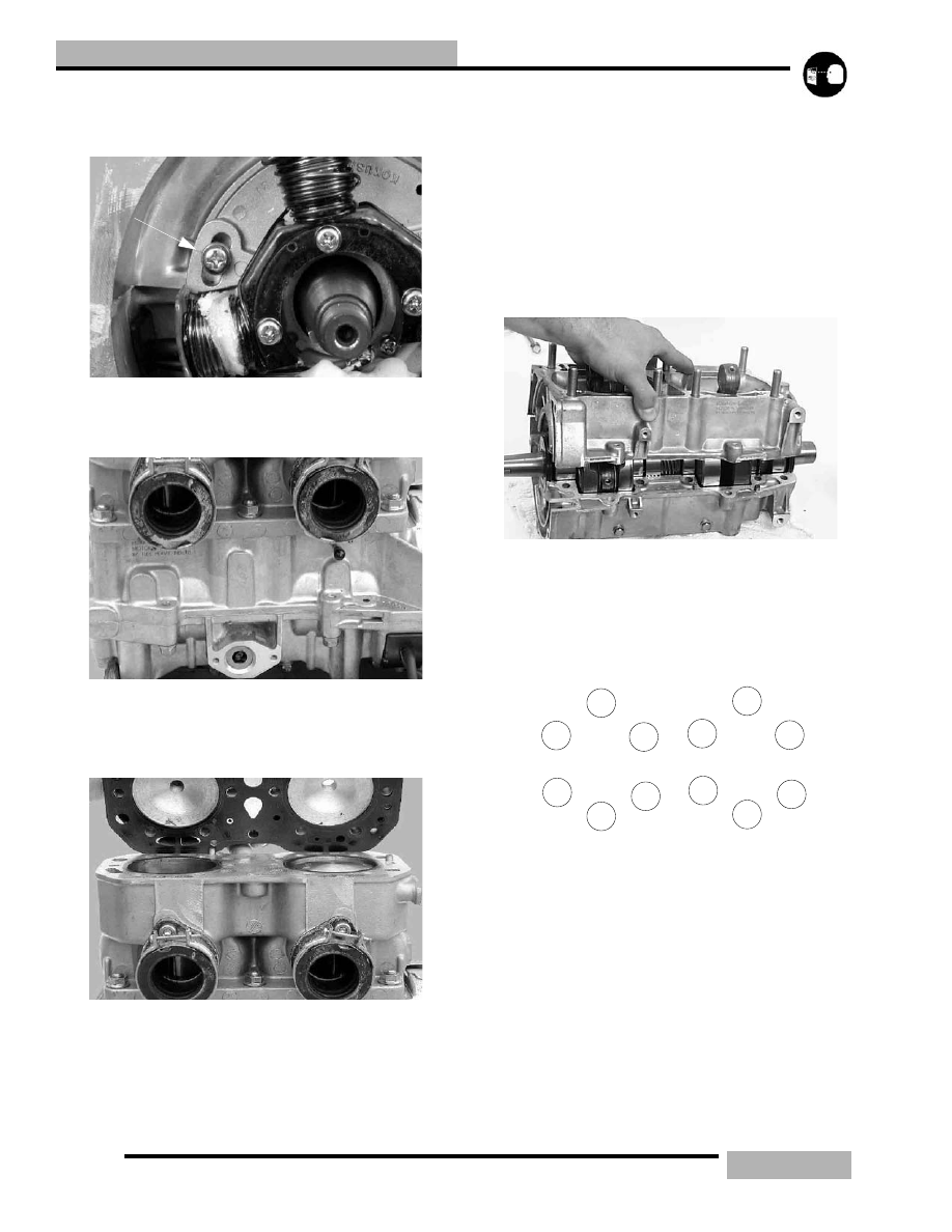
Mark stator plate and crankcase for reference when
reassembling the engine.

5.

Using a screwdriver, remove stator screws.

6.

Remove oil pump, oil pump feed lines from cylinders.
Clean and inspect all components.

7.

Remove the cylinder head.

8.

Remove head gasket. Note the position of head gasket
inlet and outlet hole sizes for reference during reassembly.
Always replace head gasket after disassembly.

9.

Remove cylinder.

10. Remove C-clip retainers from pistons.

11. Using piston pin puller, remove piston pin from piston.

12. Remove crankcase bolts. 

13. Refer to ‘INSPECTONS” on page 3.5 for engine

component inspection (i.e. crankshaft and crankcase
inspection, piston clearance, oil pump drive gear end play
etc.).

ASSEMBLY

1.

Grease oil pump drive gear area. Seals should be installed
with spring and lip facing inward toward crankshaft.

2.

Turn bearing until anti-rotation pins are positioned in the
proper location.

3.

Apply 3-Bond sealant to crankcase halves.

4.

Torque crankcase bolts following sequence outlined in
beginning of this chapter. Lubricate crankshaft main
bearings through access holes. Torque 8mm Bolts to 17-18
f.-lb (22-23Nm), and 10mm bolts to 23-25 ft-lb (32-
35Nm).

9

5

1

12

8

4

3

2

6

10

11

7

CRANKCASE PATTERN

6.31

ENGINE

5.

Install pistons with F" mark or arrow toward flywheel.

6.

Install C-clip using installation tool PN 2870773.

7.

Install new base gasket. Mount gasket with the white
sealing material facing up.

8.

Lubricate rings and pistons with two stroke oil. Install
rings with letter, mark, or beveled side facing upward.

9.

Lubricate rings and cylinder with Premium 2 Cycle
Lubricant and compress rings with fingers, aligning end
gaps with locating pins. Install cylinder with a gentle front-
to-back rocking motion, being careful not to damage rings.

10. Install cylinder base nuts in pattern and torque to 27-31 ft-

lb (37-43Nm)

11. Install head gasket. Note proper position of gasket, “UP”

facing upward, small intake hole on right (mag) side, large
hole on left (PTO) side.

7

1

3

5

4

2

6

CYLINDER BASE

6.32

ENGINE

12. Install cylinder head and torque cylinder head nuts to 18 -

19.5 ft-lb (25-27Nm) following the torque pattern.

13. Before installing oil pump drive gear, refer to Oil Pump

end play adjustment.

14. Install oil pump drive gear in the sequence shown in

diagram at the right.

15. Install oil pump.

16. Connect oil feed lines to the cylinders.

17. Align stator as previously marked on stator plate and

secure with screws.

18. Install flywheel and torque flywheel nut to 60-65 ft-lb (83-

90Nm) using the flywheel holding tool PN 8700229. 

19. Install water pump and recoil starter cup. make sure that

the thicker end of the drive pulley is towards the flywheel
as shown.

20. Adjust tension on water pump belt by loosening mounting

bolts, applying tension, and re-tightening bolts.

21. Install recoil housing and carburetors.

22. Bleed the oil pump.

23. Connect CDI to stator plug connector.

24. Pre-mix (32:1) the first tank of fuel. See ‘2 STROKE

GASOLINE / OIL PRE MIX” on page 2.10 for premix
chart.

1

2

3

4

5

6

7

9

8

10

11

12

12

14

CYLINDER HEAD TORQUE PATTERN

Gear

Spacer

Bushing

Spacers

o-ring

Engine side

Oil Pump Side

7.1

CLUTCHING

CHAPTER 7

CLUTCHING

7

SPECIAL CLUTCH TOOLS . . . . . . . . . . . . . . . . . . . . . . . . . . . . . . . . . . . . . . . . . . . . . . 7.2

CLUTCH TOOLS . . . . . . . . . . . . . . . . . . . . . . . . . . . . . . . . . . . . . . . . . . . . . . . . . . . . . . . 7.2

DRIVE BELT  . . . . . . . . . . . . . . . . . . . . . . . . . . . . . . . . . . . . . . . . . . . . . . . . . . . . . . . . . 7.3

BELT INSPECTION . . . . . . . . . . . . . . . . . . . . . . . . . . . . . . . . . . . . . . . . . . . . . . . . . . . . . 7.3
BELT DIAGNOSIS . . . . . . . . . . . . . . . . . . . . . . . . . . . . . . . . . . . . . . . . . . . . . . . . . . . . . . 7.3
DRIVE BELT REMOVAL WITH TEAM CLUTCH . . . . . . . . . . . . . . . . . . . . . . . . . . . . . . . 7.4
BELT INSTALLATION (TEAM DRIVEN CLUTCH)  . . . . . . . . . . . . . . . . . . . . . . . . . . . . . 7.4
DRIVE BELT REMOVAL WITH POLARIS DRIVEN CLUTCH. . . . . . . . . . . . . . . . . . . . . 7.5
BELT INSTALLATION (POLARIS DRIVEN CLUTCH). . . . . . . . . . . . . . . . . . . . . . . . . . . 7.5

DRIVE SYSTEM TERMINOLOGY. . . . . . . . . . . . . . . . . . . . . . . . . . . . . . . . . . . . . . . . . 7.5

SYSTEM OVERVIEW  . . . . . . . . . . . . . . . . . . . . . . . . . . . . . . . . . . . . . . . . . . . . . . . . . . . 7.6
DRIVE SPRING . . . . . . . . . . . . . . . . . . . . . . . . . . . . . . . . . . . . . . . . . . . . . . . . . . . . . . . . 7.6
CLUTCH WEIGHT . . . . . . . . . . . . . . . . . . . . . . . . . . . . . . . . . . . . . . . . . . . . . . . . . . . . . . 7.6
NEUTRAL SPEED . . . . . . . . . . . . . . . . . . . . . . . . . . . . . . . . . . . . . . . . . . . . . . . . . . . . . . 7.6
ENGAGEMENT RPM. . . . . . . . . . . . . . . . . . . . . . . . . . . . . . . . . . . . . . . . . . . . . . . . . . . . 7.6
SHIFT OUT OVERREV . . . . . . . . . . . . . . . . . . . . . . . . . . . . . . . . . . . . . . . . . . . . . . . . . . 7.6
SHIFT OUT RPM . . . . . . . . . . . . . . . . . . . . . . . . . . . . . . . . . . . . . . . . . . . . . . . . . . . . . . . 7.6
DRIVEN SPRING . . . . . . . . . . . . . . . . . . . . . . . . . . . . . . . . . . . . . . . . . . . . . . . . . . . . . . . 7.6
BACK-SHIFTING . . . . . . . . . . . . . . . . . . . . . . . . . . . . . . . . . . . . . . . . . . . . . . . . . . . . . . . 7.7
FINAL GEARING . . . . . . . . . . . . . . . . . . . . . . . . . . . . . . . . . . . . . . . . . . . . . . . . . . . . . . . 7.7
1:1 SHIFT RATIO . . . . . . . . . . . . . . . . . . . . . . . . . . . . . . . . . . . . . . . . . . . . . . . . . . . . . . . 7.7
LOW / HIGH RATIO LINES . . . . . . . . . . . . . . . . . . . . . . . . . . . . . . . . . . . . . . . . . . . . . . . 7.7
DRIVEN HELIX / RAMP . . . . . . . . . . . . . . . . . . . . . . . . . . . . . . . . . . . . . . . . . . . . . . . . . . 7.7

CENTRIFUGAL DRIVE SYSTEM . . . . . . . . . . . . . . . . . . . . . . . . . . . . . . . . . . . . . . . . . 7.8

THEORY OF OPERATION  . . . . . . . . . . . . . . . . . . . . . . . . . . . . . . . . . . . . . . . . . . . . . . . 7.8

DRIVE CLUTCH  . . . . . . . . . . . . . . . . . . . . . . . . . . . . . . . . . . . . . . . . . . . . . . . . . . . . . . 7.8

OPERATION  . . . . . . . . . . . . . . . . . . . . . . . . . . . . . . . . . . . . . . . . . . . . . . . . . . . . . . . . . . 7.8
DRIVE CLUTCH IDENTIFICATION . . . . . . . . . . . . . . . . . . . . . . . . . . . . . . . . . . . . . . . . . 7.9
DRIVE CLUTCH REMOVAL  . . . . . . . . . . . . . . . . . . . . . . . . . . . . . . . . . . . . . . . . . . . . . . 7.9
DRIVE CLUTCH COMPONENTS  . . . . . . . . . . . . . . . . . . . . . . . . . . . . . . . . . . . . . . . . . 7.10
DRIVE CLUTCH DISASSEMBLY  . . . . . . . . . . . . . . . . . . . . . . . . . . . . . . . . . . . . . . . . . 7.12
CLUTCH ASSEMBLY  . . . . . . . . . . . . . . . . . . . . . . . . . . . . . . . . . . . . . . . . . . . . . . . . . . 7.13
DRIVE CLUTCH SPIDER REMOVAL/INSTALLATION . . . . . . . . . . . . . . . . . . . . . . . . . 7.14
ROLLER REMOVAL  . . . . . . . . . . . . . . . . . . . . . . . . . . . . . . . . . . . . . . . . . . . . . . . . . . . 7.14
ROLLER INSTALLATION  . . . . . . . . . . . . . . . . . . . . . . . . . . . . . . . . . . . . . . . . . . . . . . . 7.14
SPIDER INDEXING . . . . . . . . . . . . . . . . . . . . . . . . . . . . . . . . . . . . . . . . . . . . . . . . . . . . 7.15
SPRING FREE LENGTH . . . . . . . . . . . . . . . . . . . . . . . . . . . . . . . . . . . . . . . . . . . . . . . . 7.15
DRIVE CLUTCH WEIGHTS . . . . . . . . . . . . . . . . . . . . . . . . . . . . . . . . . . . . . . . . . . . . . . 7.18
DRIVE CLUTCH INSTALLATION  . . . . . . . . . . . . . . . . . . . . . . . . . . . . . . . . . . . . . . . . . 7.19

DRIVEN CLUTCH . . . . . . . . . . . . . . . . . . . . . . . . . . . . . . . . . . . . . . . . . . . . . . . . . . . . 7.20

DRIVEN CLUTCH OVERVIEW . . . . . . . . . . . . . . . . . . . . . . . . . . . . . . . . . . . . . . . . . . . 7.20
DRIVEN CLUTCH TYPES . . . . . . . . . . . . . . . . . . . . . . . . . . . . . . . . . . . . . . . . . . . . . . . 7.20
DRIVEN CLUTCH REMOVAL . . . . . . . . . . . . . . . . . . . . . . . . . . . . . . . . . . . . . . . . . . . . 7.20
DRIVEN CLUTCH INSTALLATION . . . . . . . . . . . . . . . . . . . . . . . . . . . . . . . . . . . . . . . . 7.20
TEAM RAMPS EXPLAINED  . . . . . . . . . . . . . . . . . . . . . . . . . . . . . . . . . . . . . . . . . . . . . 7.21
POLARIS P-85 HELIX . . . . . . . . . . . . . . . . . . . . . . . . . . . . . . . . . . . . . . . . . . . . . . . . . . 7.23
DRIVEN SPRINGS  . . . . . . . . . . . . . . . . . . . . . . . . . . . . . . . . . . . . . . . . . . . . . . . . . . . . 7.24

DRIVE SYSTEM ADJUSTMENTS. . . . . . . . . . . . . . . . . . . . . . . . . . . . . . . . . . . . . . . . 7.25

CLUTCH ALIGNMENT. . . . . . . . . . . . . . . . . . . . . . . . . . . . . . . . . . . . . . . . . . . . . . . . . . 7.25
CLUTCH ALIGNMENT INSPECTION . . . . . . . . . . . . . . . . . . . . . . . . . . . . . . . . . . . . . . 7.25
CLUTCH ALIGNMENT ADJUSTMENT . . . . . . . . . . . . . . . . . . . . . . . . . . . . . . . . . . . . . 7.25
CLUTCH OFFSET . . . . . . . . . . . . . . . . . . . . . . . . . . . . . . . . . . . . . . . . . . . . . . . . . . . . . 7.25
OFF SET ADJUSTMENT . . . . . . . . . . . . . . . . . . . . . . . . . . . . . . . . . . . . . . . . . . . . . . . . 7.25


Content   ..  34  35  36  37   ..