Snowmobile Polaris (2006 year). Manual - part 35
6.26
ENGINE
The long studs are installed to a height of 3.66" (93mm). The
small studs are installed to a height of 2.16" (55mm).
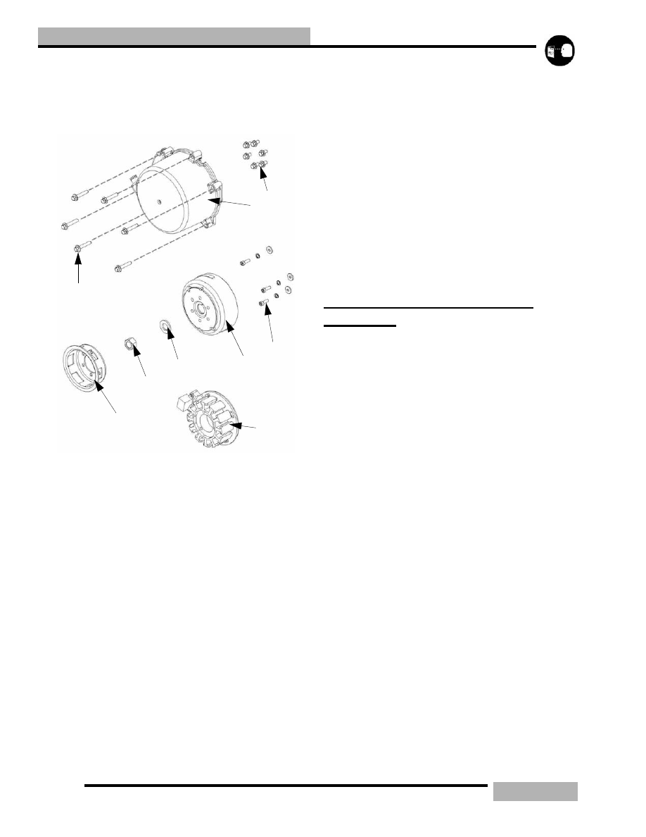
500/600 RECOIL/STATOR REMOVAL
1.
Remove the recoil cover (2).
2.
Remove the recoil basket bolts (1) and the recoil basket
(4).
3.
Using a strap wrench PN PU-45419 hold the flywheel
while taking the flywheel nut (5) and washer (6) off.
4.
Using the Flywheel Puller PN 2871043, thread the puller
bolts into the flywheel. Do not install puller bolts more
than 5/16, (7mm) into flywheel threads or stator damage
may result.
5.
Tighten the center bolt and remove the flywheel (7).
6.
Note the ignition timing marks that match up with the
stator to the crankcase or scribe additional marks for
reference for assembly.
7.
Remove the stator bolts (8), and remove the stator (9). Be
careful when removing the wires of the stator.
500/600 RECOIL/STATOR ASSEMBLY
NOTE: Inspect all parts for wear or damage during
disassembly. Replace all seals, o-rings, and gaskets
with Genuine Pure Polaris parts during assembly.
Refer General chapter for general inspection
procedures.
1.
Install the stator (9) and align the timing marks that was
noted earlier.
2.
Apply Loctite 242 to the first few threads of the stator
bolts (8) and torque to 5 ft-lb (7Nm).
3.
Install the flywheel (7) so that it matches up with the index
of the woodruff key.
4.
Apply Loctite 242 to the threads of the flywheel nut (5)
and place the washer (6) and nut onto the end of the
crankshaft.
5.
Holding the flywheel with the strap wrench, torque the
flywheel nut to 90 ft-lb (122Nm).
6.
Install the recoil basket (4) and the recoil basket bolts (3)
on the flywheel and torque the bolts to 9 ft-lb (12Nm).
7.
Install recoil assembly (2) and torque the recoil assembly
bolts (1) to 9 ft-lb (12Nm).
340/550 FUJI ENGINE/500
LIBERTY
340/550 FUJI/500 LIBERTY ENGINE
REMOVAL/INSTALLATION
1.
Turn the fuel valve to the “OFF” position.
2.
Remove the exhaust system.
3.
Disconnect the battery ground (-) if applicable.
4.
Disconnect the CDI box.
5.
Remove the spark plug leads form the spark plugs.
6.
Disconnect the stator connection(s).
7.
Remove the air box.
8.
Remove the drive belt.
9.
Remove the drive and driven clutches.
10. Remove the recoil handle and secure the rope so that it is
on the recoil housing.
11. Loosen the carburetor clamps that are holding the
carburetor onto the boots.
12. Separate the carburetors and secure them out of the way
for engine removal.
13. Disconnect the oil pump cable from the oil pump.
14. Disconnect the oil supply line at the oil pump, and plug the
end with a clean bolt.
15. Remove the fuel pump impulse line from the engine.
16. Remove all the motor mount nuts.
17. Remove the engine.
18. Install in reverse order.
1
2
4
5
6
7
8
9
3
9(12)
90(122)
5(7)