содержание .. 1 2 3 4 5 6 7 ..
Aprilia scooter (manual) - part 6
-
-
WATER TEMPERATURE SENSOR
-
REMOVING THE WATER TEMPERATURE SENSOR
-

-
-
Raise the seat, 7.1.2.
-
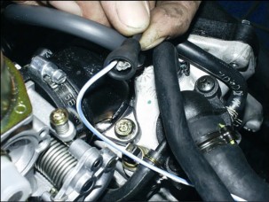
Undo and remove screw (1).
-
Remove protection.
-
Disconnect the water temperature sensor.

-
Undo and remove the water temperature sensor.

-
REMOVING THE EXPANSION RESERVOIR
-
REMOVING THE EXPANSION RESERVOIR
-

-
-
Drain the cooling system, 5.2.1.

-
Release the expansion reservoir from the support
7.1.16.
-
Remove the two cooling system tubes.
-
Remove the expansion reservoir.
ENGINE 6
![]()
SUMMARY
-
EXHAUST SYSTEM 3
-
EXHAUST SILENCER REMOVAL 3
-
EXHAUST SYSTEM REMOVAL 4
-
ENGINE COMPONENTS THAT CAN BE REMOVED LEAVING THE ENGINE IN THE FRAME 5
-
-
ENGINE 6
-
ENGINE REMOVAL 6
-
INSTALLING THE ENGINE INTO THE FRAME 9
-

-
EXHAUST SYSTEM
-
EXHAUST SILENCER REMOVAL TORQUE WRENCH SETTINGS
Clamp (1) 20 Nm (2.0 kgm)
Screws (2) 25 Nm (2.5 kgm)
-
Place the vehicle on the centre stand.
 DANGER
Allow some time for the engine and the exhaust
silencer to cool down completely.
-
Slacken the clamp (1) securing the exhaust silencer to the manifold.
-
Release and remove the three retaining screws (2).
-
Remove the exhaust silencer.
-
-
EXHAUST SYSTEM REMOVAL
-
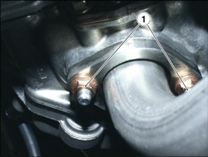
TORQUE WRENCH SETTINGS
Nuts (1) 18 Nm (1.8 kgm)
Screws (2) 25 Nm (2.5 kgm)
![]() DANGER
DANGER
Allow some time for the engine and the exhaust
silencer to cool down completely.
-
Remove the air dam.
-
Release and remove the two nuts (1).

-
Release and remove the three retaining screws (2).
-
Remove the exhaust system.
6.1.3. ENGINE COMPONENTS THAT CAN BE REMOVED LEAVING THE ENGINE IN THE FRAME
The components listed below can be removed and refitted with no need to take the engine out of the frame.
LEFT SIDE OF ENGINE
-
Transmission casing cover
-
Automatic converter
-
Clutch assembly
-
Drive belt
RIGHT SIDE OF ENGINE
-
Spark plug
-
Flywheel
-
Ignition casing
-
Stator coil
-
Pick-up
-
Coolant pump
-
Secondary air system
TOP END OF ENGINE
-
Carburetor
-
Intake manifold hose
-
Starter motor
-
Coolant thermistor
-
Thermal expansion valve
-
Timing chain tensioner
FRONT END OF ENGINE
-
Valve tappet cover
-
Camshaft
-
Cylinder head
-
Cylinder
-
Piston
BOTTOM END OF ENGINE
-
Exhaust silencer
-
Engine oil filter
-
ENGINE

-
ENGINE REMOVAL Read 1.2.1. carefully.
TORQUE WRENCH SETTINGS
Lower bolt (9) 50 Nm (5.0 kgm)
 WARNING
The engine is removed by lowering it from the
frame. Make sure to have all necessary equipment ready at hand and in place before proceeding.


Before taking the engine out of the frame, clean it with a steam cleaner and drain all coolant, see 5.2.1.
NOTE Certain procedures include cross-references to relevant sections of the manual. Some of the operations described there may not be strictly required for the job at hand. Proceed sensibly to avoid redundant work, that is, always make sure you really need to remove a particular component before proceeding.

Engine removal procedures are listed in the proper sequence in this section.
-
Remove the helmet compartment, 7.1.16.
-
Remove the carburetor, 4.3.1.

-
Remove the exhaust system, 6.1.2.
-
Remove the calliper from the rear brake disc, 7.6.2.
-
Release and remove the screw (1) and disconnect the grounding cable from the starter motor.
-
Release and remove the nut (2) and disconnect the cable from the starter motor.

-
Disconnect the connector (3) at the coolant temperature sensor end.
-
Disconnect the pick-up (4).

-
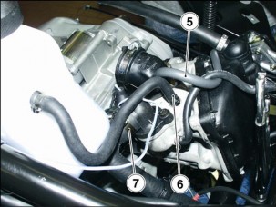
Disconnect the vacuum hose (5) from the intake manifold.
-
Withdraw the drain hose (6) from the head.
-
Disconnect the hose (7) from the thermal expansion valve.
-
Disconnect the hose (8) from the coolant pump.


-
Release and remove the lower bolt (9).
-
Disconnect the spark plug cap.


NOTE You will need a hoist and suitable slings to lift the engine.
-
Fix the slings to the rear end of the frame.
-
Lift the hoist arm until stretching the slings taut.
-
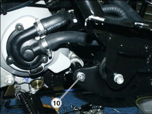
Working from the right side, release and remove the nut (10).

-
Withdraw the bolt (11) from the opposite side and collect washer and spacer.
-
Remove the engine complete with centre stand and rear wheel.


-
-
INSTALLING THE ENGINE INTO THE FRAME Read 1.2.1. carefully.
-
TORQUE WRENCH SETTINGS
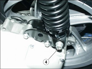
Lower mounting bolt (4) 50 Nm (5.0 kgm)
![]() DANGER
DANGER
Handle the engine with care and be careful of
your finger and limbs.
-
Shift the engine in small motions until matching the mounting holes perfectly.
-
Insert the bolt (1) from the left side with washer and spacer.

-
Tighten the nut (2) at the opposite end.
-
Fit the hose (3) to the coolant pump.
-
Secure the hose (3) with the clamp.
-
Tighten the shock absorber lower bolt (4).

-
Fit the vacuum hose (5) to the intake manifold.
-
Fit the drain hose (6) to the head.
-
Fit the hose (7) to the thermal expansion valve.

-
Connect the following electric connectors in the order:
-
Pick-up (8).
-
-
Coolant temperature sensor (9).


-
Position the grounding cable of the starter motor.
-
Tighten the screw (10).
-
Position the power supply cable of the starter motor.

-
Tighten the nut (11).
-
Fit the calliper to the rear brake disc, 7.6.2.
-
Install the exhaust system, see 6.1.2.
-
Install the carburetor, see 4.3.1.
-
Install the helmet compartment, 7.1.16.
-
Top up coolant level, see 2.9.1.
NOTE Inspect any components you have disturbed and check that:
-
electric leads are secured correctly with the suitable ties;
![]() WARNING
WARNING
The leads should not be twisted or trapped
under any components.
-
electric connectors are connected to the matching connectors;
-
hoses and hose couplings are inserted correctly and fixed with suitable clips;
-
throttle and cold-start cables slide freely and do not bind when you turn the handlebar.
CHASSIS 7
![]()
SUMMARY
-
BODYWORK 4
-
BODYWORK 4
-
SADDLE REMOVAL 6
-
REMOVING THE REAR SIDE PANELS 7
-
LUGGAGE RACK REMOVAL 8
-
TAIL REMOVAL 9
-
REMOVING THE NUMBER PLATE HOLDER 10
-
REMOVING THE CENTRAL TUNNEL 11
-
AIR DAM REMOVAL 13
-
LEGSHIELD REMOVAL 15
-
FRONT COVER REMOVAL 16
-
SCREEN REMOVAL 17
-
REAR-VIEW MIRROR REMOVAL 18
-
REMOVING THE SIDE FAIRINGS 19
-
FRONT MUDGUARD REMOVAL 20
-
REAR MUDGUARD REMOVAL 21
-
HELMET COMPARTMENT REMOVAL 22
-
HANDLEBAR COVER REMOVAL 23
-
SPLASHGUARD REMOVAL 25
-
BATTERY REMOVAL 26
-
ENGINE CONTROL UNIT REMOVAL 27
-
VOLTAGE REGULATOR REMOVAL 28
-
REMOVING THE RIGHT SWITCH 29
-
REMOVING THE LEFT SWITCH 30
-
DASHBOARD REMOVAL 31
-
HEADLIGHT REMOVAL 33
-
REMOVING THE FRONT DIRECTION INDICATORS 34
-
REMOVING THE TAIL LIGHT UNIT 35
-
COIL REMOVAL 36
-
-
CONTROLS 37
-
THROTTLE CONTROL REMOVAL 37
-
REMOVING THE REAR BRAKE MASTER CYLINDER 38
-
-
FRAME 39
-
HANDLEBAR REMOVAL 39
-
REMOVING THE DASHBOARD/WINDSHIELD MOUNTING BRACKET 40
-
SIDE STAND REMOVAL 43
-
CENTRE STAND REMOVAL 44
-
FRAME REMOVAL 45
-
-
FRONT WHEEL 47
-
FRONT WHEEL DIAGRAM 47
-
FRONT WHEEL REMOVAL 48
-
FRONT WHEEL DISASSEMBLY 50
-
INSPECTING THE FRONT WHEEL COMPONENTS 51
-
REFITTING THE FRONT WHEEL 52
-
-
REAR WHEEL 53
-
REAR WHEEL DIAGRAM 53
-
REAR WHEEL REMOVAL 54
-
-
BRAKES 56
-
BRAKES DIAGRAM 56
-
REPLACING THE FRONT BRAKE PADS 57
-
FRONT BRAKE DISC INSPECTION 58
-
FRONT BRAKE DISC REMOVAL 59
-
REPLACING THE REAR BRAKE PADS 60
-
REAR BRAKE DISC INSPECTION 61
-
REAR BRAKE DISC REMOVAL 62
-
PROPORTIONING VALVE REMOVAL 63
-
-
HEADSTOCK 64
-
HEADSTOCK REMOVAL 64
-
COMPONENT INSPECTION 65
-
-
FRONT FORK 66
-
FRONT FORK DIAGRAM 66

7 - 2
-
REMOVING THE STANCHION TUBES AND SLIDERS 67
-
DISASSEMBLING THE STANCHION TUBES AND SLIDERS 68
-
DRAINING THE FRONT FORK 71
-
FILLING THE FORK 73
-
COMPONENT INSPECTION 75
-
REFITTING THE STANCHION TUBES AND SLIDERS 76
-
-
REAR SUSPENSION 78
-
SHOCK ABSORBER REMOVAL 78
-
REMOVING THE LINKAGES 79
-
содержание .. 1 2 3 4 5 6 7 ..