содержание .. 1 2 3 4 5 6 7 ..
Aprilia scooter (manual) - part 4
-
-
THROTTLE
-
THROTTLE
Inspect after the first 1000 km (621 mi) and then every 6000 km (3728 mi) or 8 months.
CHECKING FOR THROTTLE PROPER OPERATION
 DANGER
Throttle operation may be impaired when the
throttle cables are damaged, bent in tight turns or twisted. Using the motorcycle in this condition may lead to loss of control while riding.
-
-
-
Turn the handlebars and ensure that idling speed is unaffected by handlebar movement. Open the throttle and ensure that the twistgrip springs back to the closed position smoothly when released.
If needed:
-
Make sure the components listed below are in the proper position and well lubricated:
-
sheaths;
-
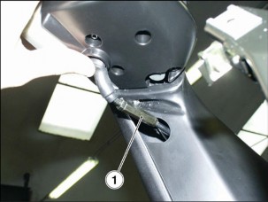
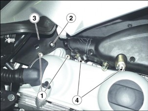
twistgrip adjuster (1);
Lubricate Bowden cable with silicone spray.
-
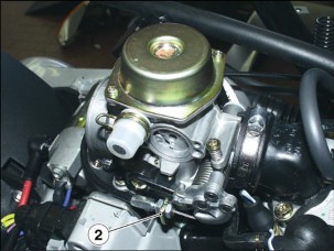
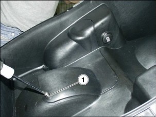
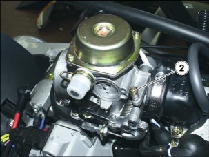
throttle body adjuster (2), under the seat;
 THROTTLE
CONTROL ADJUSTMENT
THROTTLE
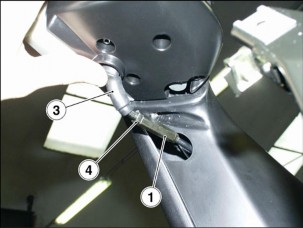
CONTROL ADJUSTMENTNOTE To adjust throttle control, turn twistgrip adjuster (1) or throttle body adjuster (2).
There should be 2–3 mm free play in the throttle twistgrip cable (measured at twistgrip edge).
If not so:
-
-
Place the motorcycle on the center stand.
-
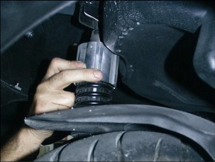
Slip off the rubber gaiter (3).
-
Loosen the locknut (4).
-
Rotate the adjuster (1) until setting the specified free play.
-
After adjusting, tighten the locknut (4) and check free play again.
-
Refit the rubber gaiter (3).

 WARNING
Turn the handlebars and ensure that idling
speed is unaffected by handlebar movement. Open the throttle and ensure that the twistgrip springs back to the closed position smoothly when released.
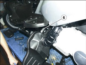
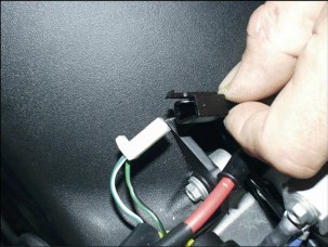
If twistgrip adjuster is fully tightened, loose or in case correct free play is not reached, proceed as follows:
-
Raise the seat.
-
Undo and remove screw (5).
-
Remove protection.
-
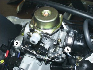
Loosen locknut (6).
-
Turn throttle adjuster (2) to restore recommended value.
-
Once finished, tighten locknut (6) and check free play again.
-
IDLING ADJUSTMENT
Adjust as follows whenever idling speed seems erratic. Proceed as follows:
-
-
Ride a few kilometers until warming engine up to regular operating temperature.
-
Raise the seat.
-
Undo and remove the screw (1).
-
Remove the protection.
-
Connect an electronic rev counter to the spark plug cable.
-
Start the engine.
Engine idling speed should be about:
- 1750 ± 100 rpm;
In this case the engine does not make the rear wheel turn.
-
Turn the screw (2).
-
ROTATE CLOCKWISE to decrease rpm.
-
ROTATE ANTI-CLOCKWISE, to increase rpm.
-
-
Flip the throttle twistgrip open and closed repeatedly to check for proper operation. Idling speed should remain stable.
-
FRONT END
-
STEERING
Inspect after the first 1000 km (621 mi) and then every 6000 km (3728 mi) or 8 months.
The steering is fitted with rolling bearings to ensure smooth handling.
Proper steering adjustment is vital to smooth steering movement and safe riding. Any hardness in the steering will impair handling, whereas a soft steering will result in poor stability.

CHECKING PLAY IN THE BEARINGS
-
-
-
Put the vehicle on the center stand.
-
Fit a mount under frame.
-
Rock the fork back and forth in the direction of travel.
-
If you feel any play, adjust the bearings.

ADJUSTING PLAY IN THE BEARINGS
TIGHTENING TORQUE SETTINGS
Check nut (1): 110 Nm (11.0 kgm).

-
Remove the leg guard, 7.1.9.
-
Loosen check nut (1).
 WARNING
Not to damage the steering bearings, take care
do not overscrew or overtighten the adjusting nut (2).
-
Screw the adjusting nut (2) until taking up bearing play.
-
To check existing play, shake fork in the direction of travel and check that the steering is smooth and free to rotate.
-
Hold the adjusting nut (2) in position and, using a wrench, tighten check nut (1).
-
Repeat the last one operation.
-
FRONT SUSPENSION
The front suspension is managed by a hydraulic fork, which is held to the steering stem by two yokes.
NOTE Vehicle set-up may not be modified.
Inspect front suspension after the first 1000km (621 mi), and then every 6000 km (3728 mi) or 8 months.
Change front fork oil every 12000 km (7456 mi) or 16 months.
Check as follows:
-
-
Keep the front brake lever squeezed in and press down repeatedly on the handlebars to compress the front fork. The front fork should compress in a smooth motion. Inspect the fork legs for any traces of oil.


If the front fork has a tendency to bottom out, change oil; see
7.9.4. and 7.9.5.
Check the front fork for oil leaks and inspect the surface of the fork legs for cracks or scoring.

Any damaged components should be repaired or – where repair is not feasible – renewed; see 7.9.6.
-
Ensure that all parts are properly tightened and test the
front suspension for proper operation.

-
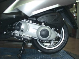
REAR AXLE
-
CHECKING THE ENGINE AXLE
Check the clearance between the engine shaft bushes and the engine shaft.
To check, proceed as follows:
-
-
-
Position the vehicle on the center stand.
-
Shake the wheel at right angles with the direction of travel.
-
In case of clearance, check for all axle parts correct tightening.
-
REAR SUSPENSION INSPECTION
Inspect the rear suspension after the first 1000 km (621 mi), and then every 6000 km (3728 mi) or 8 months.
Check that no oil leaks out of shock absorbers.
Check that all rear suspension parts are correctly tightened and joints are properly working.
REAR SUSPENSION ADJUSTMENT
The rear suspension consists of a shock absorber with two functions (compression/rebound braking), connected to the frame through silent-blocks.
Factory setting is designed to suit the broadest possible range of riding conditions, meaning low and high speed, whether riding solo or carrying a full load.
However, rear suspension setting may be modified to suit specific needs in accordance with vehicle usage:
Turn the adjuster nut to set desired riding conditions (see table).
REAR SUSPENSION SETTING TABLE
Adjuster nut
Tighten
Slacken
Purpose
Increase spring preolad
Decrease spring preload
Recommended for
Riding with a passenger
Riding solo
-
WHEELS


-
WHEELS Carefully read 1.2.1.
-
FRONT WHEEL
Check every 6000 km (3728 mi).
-
-
Place the vehicle on the center stand.
-
Place a mount under frame.
-
Rotate the wheel manually in both directions.


-
The wheel should be spinning smoothly, with no hardness or unusual noise. If not so, change the bearings; see 7.5.3.

-
If you detect any wobble, inspect wheel and affected

components; see 7.5.4.
-
A spinning wheel that always stops in exactly the same position needs balancing.
REAR WHEEL
Check every 6000 km (3728 mi).
-
Place the vehicle on the center stand.
-
Rotate the wheel manually in both directions.
7.6.3.
-
The wheel should be spinning smoothly, with no hardness or unusual noise. If not so, change the bearings.

7.6.5.

-
If you detect any wobble, inspect wheel and affected
components.
-
A spinning wheel that always stops in exactly the same position needs balancing.
-
TYRES
-
TYRES
-
Check tyre condition every month.
It is a good rule to measure tyre inflation pressures before and after a long trip.
Tyre inflation pressures should be checked monthly with the tyres at ambient temperature.
This vehicle is fitted with tubeless tyres.


For inflating pressures, see 7.6.5.

TREAD CONDITION
 WARNING
Inspect tread surface and check for wear. Badly
worn tyres adversely affect traction and handling.
Always change a worn tyre. A tyre that becomes punctured in the tread area should be changed when the puncture is larger than 5 mm.
Some of the tyre types approved for this vehicle are fitted with wear indicators.
There are various types of wear indicators. Enquire about correct wear inspection procedure with your supplier.
Never use tube tyres on tubeless tyre rims, or viceversa.
Always check that the caps are in place on the valves (1), or the tyres may deflate suddenly.
Tyre replacement and repair, and wheel servicing and balancing are delicate operations. They should be carried out using adequate tools and are best left to experienced mechanics.
The wheel must be balanced after each tyre repair.
New tyres may be coated with an oily film. Drive carefully until covering several kilometres. Never apply non-specific products to the tyres.
Approved tyre sizes are reported in the registration document. Installing non-approved tyres is a legal offence.
Using tyres other than the specified sizes may change vehicle behaviour, impair handling and make the vehicle unsafe to ride.


Use only the first-equipment tyre types selected by aprilia; see 1.7.1.
MINIMUM RECOMMENDED TREAD DEPTH (A):
Front and rear tyre 2 mm (2 mm).
-
EXHAUST SYSTEM
-
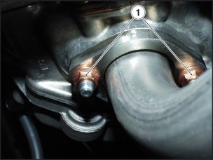
EXHAUST MANIFOLD NUTS
-
Tighten the exhaust manifold nuts after the first 1000 km (621 mi) and every 6000 km (3728 mi) or 8 months.
 DANGER
Allow the engine to cool down to ambient
temperature.
-
-
Tighten the two nuts (1) of the exhaust manifold.
LUBRICATION 3
![]()
LUBRICATION
ATLANTIC 125 - 200
SUMMARY
-
LUBRICATION 3
-
LUBRICATION 3
-
![]()
3 - 2
-
LUBRICATION
-
LUBRICATION
-
![]()
The lubrication system is described in the engine workshop manual, 0.1.2.
FUEL SYSTEM 4
SUMMARY
-
FUEL SUPPLY 3
-
FUEL SUPPLY DIAGRAM 3
-
CHANGING THE FUEL FILTER 4
-
REMOVING THE FUEL TANK 5
-
REMOVING THE FUEL SENSOR 6
-
-
AIR FILTER 7
-
REMOVING THE AIR BOX 7
-
REMOVING THE AIR CLEANER 8
-
-
CARBURETOR 9
-
REMOVING THE CARBURETOR 9
-
CARBURETOR DISASSEMBLY 11
-
ASSEMBLING THE CARBURETOR 14
-
CHECKING THE AUTOMATIC STARTER 19
-
ADJUSTING THE IDLING MIXTURE. 20
-
-
FUEL SUPPLY
-
FUEL SUPPLY DIAGRAM
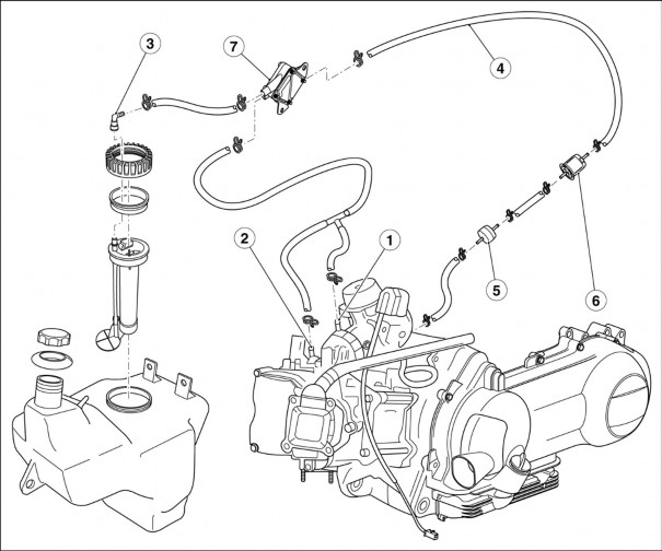
Key:
-
Vacuum ports.
-
SAI valve.
-
Fuel tank connection.
-
Pump delivery.
-
Fuel filter.
-
Anti-flow valve .
-
Vacuum fuel pump.

-
-
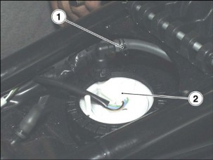
CHANGING THE FUEL FILTER


Carefully read 1.2.1. and 1.3.1.
-
Put a cloth under the fuel filter.
-
Release the two clips (1).
-
Remove the fuel filter (2).
NOTE Install a new filter of the same type fitted originally.
-
-
REMOVING THE FUEL TANK

-
Lower the cooler, but leave it connected to the coolant delivery and return pipes, 5.3.1.
-
Disconnect the fuel delivery pipe (1).
-
Disconnect the fuel sensor connector (2).

-
Undo and remove the two rear screws (3). Keep the washers.
-
Lower and remove the fuel tank.

-
-
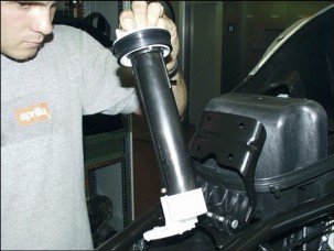
REMOVING THE FUEL SENSOR

-
Remove the central tunnel, 7.1.7.
-
Disconnect the fuel delivery pipe (1).
-
Disconnect the fuel sensor connector (2).
-
Undo and remove ring nut (3).

-
To remove fuel sensor, turn and lift it.
-
-
-
AIR FILTER
-
REMOVING THE AIR BOX TIGHTENING TORQUE SETTINGS
Screws (4) 8 Nm (0.8 Kgm).
-
Undo and remove the two screws (1).
-
Undo and remove screw (2).
-
Remove the engine breather pipe protection (3).
-
Undo and remove the two screws (4).

-
Loosen cable tie (5) and slide intake line out of carburetor.
-
Move the filter box aside.
-
Slide the engine breather pipe (6) out of air box.
-
Remove air box.

-
-
REMOVING THE AIR CLEANER

-
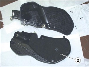
Remove the air box, 4.2.1.
-
Undo and remove the nine screws (1).
-
Open the air box.
-
Remove the air cleaner (2).
-
-
-
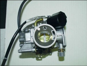
CARBURETOR
-
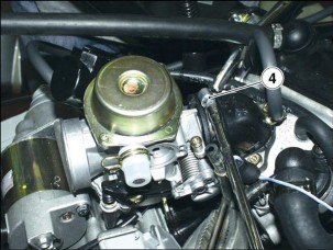
REMOVING THE CARBURETOR


-
Remove the air filter box, 4.2.1.
-
Raise the seat, 7.1.2.
-
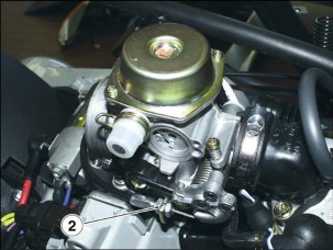
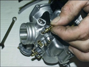
Undo and remove screw (1).
-
Remove protection.
-
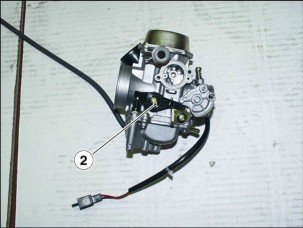
Loosen check nut (2).
-
Remove throttle cable from carburetor.

-
Squash the two cooling lines (3).
-
Slide the two cooling lines (3) out of the carburetor.
-
Block off the two lines (3) to avoid coolant from leaking out.
-
Disconnect the starter connector.
-
Loosen clamp and disconnect fuel line.

-
Loosen intake manifold clamp (4).
-
Remove carburetor.

-
-
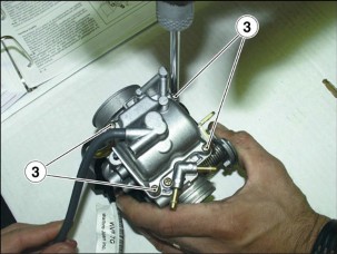
CARBURETOR DISASSEMBLY
-
Turning the two screws (1), remove protection, bracket and starter.
-
Remove fastening screw (2) and pick-up pump rocker arm and spring.

-
Remove the two retaining screws, the vacuum chamber cover and the spring.
NOTE When removing the cover, take care not to make the spring suddenly come out.
-
Remove the vacuum valve with membrane.
-
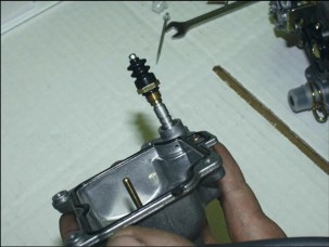
Remove the four screws (3) and the float chamber with seal.
-
Remove pick-up pump piston with ring nut, guard, OR- seal and spring from float chamber.

-
Use a suitable pin and hammer to support the carburetor and, working from the throttle control side, remove the float pin.
-
Remove float and metering rod.
-
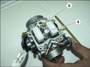
Remove the fuel conveyor cap from the starter jet (4)
-
Remove the full-power jet (5).
-
Remove diffuser.
-
Remove spray nozzle.
NOTE The spray nozzle will thus not be lost when cleaning the carburetor body. If the spray nozzle is friction-fitted into its location, do not remove it to avoid damage.
-
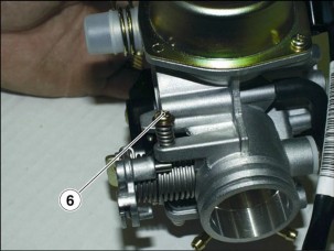
Remove the idling jet (6).
-
Remove the idle flow screw with OR-seal, washer and spring.
 WARNING
Do not remove the parts driven into the
carburetor body, such as fuel delivery duct, needle location, starter jet, progression recess cap and full-power jet, throttle control shaft. Do not remove the throttle-to-shaft jointing screws. Screws have been caulked after fitting and, if removed, will cause shaft damage.
-
-
содержание .. 1 2 3 4 5 6 7 ..