Volvo V70X, C70 (2010 year). Instruction - part 15


  Index      Volvo     Volvo V70X, C70 - instruction 2010 year in english


Search            


Content   ..  13  14  15  16   ..


Volvo V70X, C70 (2010 year). Instruction - part 15


06 Maintenance and specifications

 Wheels and tires

06

``

245

NOTE

The placards shown indicate inflation
pressure for the tires installed on the
vehicle at the factory only.

A certain amount of air seepage from
the tires occurs naturally and tire pres-
sure fluctuates with seasonal changes
in temperature. Always check tire pres-
sure regularly.

Use a tire gauge to check the tire inflation
pressure, including the spare, at least once
a month and before long trips. You are
strongly urged to buy a reliable tire pres-
sure gauge, as automatic service station
gauges may be inaccurate.

Use the recommended cold inflation pres-
sure for optimum tire performance and
wear.

Under-inflation or over-inflation may cause
uneven treadwear patterns.

NOTE

A certain amount of air seepage from the
tires occurs naturally and tire pressure fluc-
tuates with seasonal changes in tempera-
ture. Always check tire pressure regularly.

WARNING

Under-inflation is the most common
cause of tire failure and may result in
severe tire cracking, tread separation,
or "blow-out," with unexpected loss of
vehicle control and increased risk of
injury.

Under-inflated tires reduce the load car-
rying capacity of your vehicle.
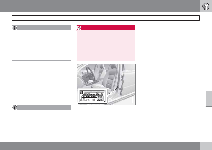
G032522

Tire inflation placard on Canadian models

When weather temperature changes occur, tire
inflation pressures also change. A 10-degree
temperature drop causes a corresponding
drop of 1 psi (7 kPa) in inflation pressure. Check
your tire pressures frequently and adjust them
to the proper pressure, which can be found on

the vehicle's tire information placard or certifi-
cation label.

Checking tire pressure

Cold tires

Inflation pressure should be checked when the
tires are cold.

The tires are considered to be cold when
they have the same temperature as the sur-
rounding (ambient) air.

This temperature is normally reached after the
vehicle has been parked for at least 3 hours.

After driving a distance of approximately
1 mile (1.6 km), the tires are considered to be
hot. If you have to drive farther than this dis-
tance to pump your tire(s), check and record
the tire pressure first and add the appropriate
air pressure when you get to the pump.

If checking tire pressure when the tire is hot,
never "bleed" or reduce air pressure. The tires
are hot from driving and it is normal for pres-
sures to increase above recommended cold
pressures. A hot tire at or below recommended
cold inflation pressure could be significantly
under-inflated.

06 Maintenance and specifications

Wheels and tires 

06

246

To check inflation pressure:

1.

Remove the cap from the valve on one tire,
then firmly press the tire gauge onto the
valve.

2.

Add air to reach the recommended air
pressure.

3.

Replace the valve cap.

4.

Repeat this procedure for each tire, includ-
ing the spare.

5.

Visually inspect the tires to make sure there
are no nails or other objects embedded
that could puncture the tire and cause an
air leak.

6.

Check the sidewalls to make sure there are
no gouges, cuts, bulges or other irregular-
ities.

NOTE

If you overfill the tire, release air by
pushing on the metal stem in the center
of the valve. Then recheck the pressure
with your tire gauge.

Some spare tires require higher inflation
pressure than the other tires. Consult
the tire inflation tables or see the infla-
tion pressure placard.

Tire specifications

Speed ratings

The speed ratings in the table translate as fol-
low:

Speed ratings

M

81 mph (130 km/h)

Q

100 mph (160 km/h)

T

118 mph (190 km/h)

H

130 mph (210 km/h)

V

149 mph (240 km/h)

W

168 mph (270 km/h)

Y

186 mph (300 km/h)

Load ratings

The speed ratings in the table translate as fol-
low:

Load ratings

91

1365 lbs (615 kg)

93

1433 lbs (650 kg)

99

1709 lbs (755 kg)

See also page 248 for an explanation of the
designations on the sidewall of the tire.

06 Maintenance and specifications

 Wheels and tires

06

``

247

Tire inflation pressure table – U.S. models

The following tire pressures are recommended by Volvo for your vehicle. Refer to the tire inflation placard for information specific to the tires installed
on your vehicle at the factory.

Tire size

Cold tire pressure for up to 5 persons

Front

psi/kPa

Rear

psi/kPa

225/55 R 16

225/50 R 17

245/45 R 17

35/240

35/240

T 125/80 R 17

61/420

61/420

Tire inflation pressure table – Canadian models

The following tire pressures are recommended by Volvo for your vehicle. Refer to the tire inflation placard for information specific to the tires installed
on your vehicle at the factory.

Tire size

Cold tire pressure for up to 5 persons

Optional tire pressure for up to 3 persons

Front

psi/kPa

Rear

psi/kPa

Front

psi/kPa

Rear

psi/kPa

225/55 R16

225/50 R 17

245/45 R 17

38/260

38/260

33/230

33/230

T 125/80 R 17

61/420

61/420

61/420

61/420

06 Maintenance and specifications

Wheels and tires 

06

248

Tire designations

3

10

11

12

4

5

6

7

8

9

2

1

G010753

Federal law mandates that tire manufacturers
place standardized information on the sidewall
of all tires (see the illustration).

The following information is listed on the tire
sidewall:

The tire designation:

NOTE

Please be aware that the following tire des-
ignation is an example only and that this
particular tire may not be available on your
vehicle.

1.

215: the width of the tire (in millimeters)
from sidewall edge to sidewall edge. The
larger the number, the wider the tire.

2.

65: The ratio of the tire's height to its width.

3.

R: Radial tire.

4.

15: The diameter of the wheel rim (in
inches).

5.

95: The tire's load index. In this example, a
load index of 95 equals a maximum load of
1521 lbs (690 kg).

6.

H: The tire's speed rating, or the maximum
speed at which the tire is designed to be
driven for extended periods of time, carry-
ing a permissible load for the vehicle, and
with correct inflation pressure. For exam-
ple, H indicates a speed rating of 130 mph
(210 km/h).

NOTE

This information may not appear on the tire
because it is not required by law.

7.

M+S or M/
S
 = Mud and Snow, AT = All Terrain,
AS = All Season

8.

U.S. DOT Tire Identification Number
(TIN)
: This begins with the letters "DOT"
and indicates that the tire meets all federal
standards. The next two numbers or letters
are the plant code where it was manufac-
tured, the next two are the tire size code
and the last four numbers represent the
week and year the tire was built. For exam-
ple, 2501 means the 25th week of 2001.
The numbers in between are marketing
codes used at the manufacturer's discre-
tion. This information helps a tire manufac-
turer identify a tire for safety recall purpo-
ses.

9.

Tire Ply Composition and Material
Used
: Indicates the number of plies indi-
cates or the number of layers of rubber-
coated fabric in the tire tread and sidewall.
Tire manufacturers also must indicate the
ply materials in the tire and the sidewall,
which include steel, nylon, polyester, and
others.

10. Maximum

Load: Indicates the maximum load in
pounds and kilograms that can be carried
by the tire. Refer to the vehicle's tire infor-
mation placard located on the B-Pillar for
the correct tire pressure for your vehicle.

06 Maintenance and specifications

 Wheels and tires

06

``

249

11. Treadwear, Traction, and Temperature

grades: See page 251 for more informa-
tion.

12. Maximum permissible inflation pressure:

the greatest amount of air pressure that
should ever be put in the tire. This limit is
set by the tire manufacturer.

Glossary of tire terminology

The tire suppliers may have additional mark-
ings, notes or warnings such as standard load,
radial tubeless, etc.

Tire information placard: A placard
showing the OE (Original Equipment) tire
sizes, recommended inflation pressure,
and the maximum weight the vehicle can
carry.

Tire Identification Number (TIN): A num-
ber on the sidewall of each tire providing
information about the tire brand and man-
ufacturing plant, tire size and date of man-
ufacturer.

Inflation pressure: A measure of the
amount of air in a tire.

Standard load: A class of P-metric or Met-
ric tires designed to carry a maximum load
at 35 psi [37 psi (2.5 bar) for Metric tires].
Increasing the inflation pressure beyond
this pressure will not increase the tires load
carrying capability.

Extra load: A class of P-metric or Metric
tires designed to carry a heavier maximum
load at 41 psi [43 psi (2.9 bar) for Metric
tires]. Increasing the inflation pressure
beyond this pressure will not increase the
tire's load carrying capability.

kPa: Kilopascal, a metric unit of air pres-
sure.

PSI: Pounds per square inch, a standard
unit of air pressure.

B-pillar: The structural member at the side
of the vehicle behind the front door.

Bead area of the tire: Area of the tire next
to the rim.

Sidewall of the tire: Area between the
bead area and the tread.

Tread area of the tire: Area of the perim-
eter of the tire that contacts the road when
mounted on the vehicle.

Rim: The metal support (wheel) for a tire or
a tire and tube assembly upon which the
tire beads are seated.

Maximum load rating: a figure indicating
the maximum load in pounds and kilo-
grams that can be carried by the tire. This
rating is established by the tire manufac-
turer.

Maximum permissible inflation
pressure
: the greatest amount of air pres-

sure that should ever be put in the tire. This
limit is set by the tire manufacturer.

Recommended tire inflation pressure:
inflation pressure, established by Volvo,
which is based on the type of tires that are
mounted on a vehicle at the factory. This
inflation pressure is affected by the number
of occupants in the vehicle, the amount of
cargo, and the speed at which the vehicle
will be driven for a prolonged period. This
information can be found on the tire infla-
tion placard(s) located on the driver's side
B-pillar and in the tire inflation table in this
chapter.

Cold tires: The tires are considered to be
cold when they have the same temperature
as the surrounding (ambient) air. This tem-
perature is normally reached after the vehi-
cle has been parked for at least 3 hours.

Vehicle loading

Properly loading your vehicle will provide maxi-
mum return of vehicle design performance.

Before loading your vehicle, familiarize yourself
with the following terms for determining your
vehicle's weight ratings, with or without a
trailer, from the vehicle's Federal/Canadian
Motor Vehicle Safety Standards (FMVSS/
CMVSS) label, and the vehicle's tire informa-
tion placard:

06 Maintenance and specifications

Wheels and tires 

06

250

Curb weight

The weight of the vehicle including a full tank
of fuel and all standard equipment. It does not
include passengers, cargo, or optional equip-
ment.

Capacity weight

All weight added to the curb weight, including
cargo and optional equipment. When towing,
trailer hitch tongue load is also part of cargo
weight.

NOTE

For trailer towing information, please refer to
the section "Towing a trailer", see
page 208.

Permissible axle weight

The maximum allowable weight that can be
carried by a single axle (front or rear). These
numbers are shown on the Federal/Canadian
Motor Vehicle Safety Standards (FMVSS/
CMVSS) label. The total load on each axle must
never exceed its maximum permissible weight.

Gross vehicle weight (GVW)

The vehicle's curb weight + cargo + passen-
gers.

NOTE

The location of the various labels in your
vehicle can be found on page 268.

A table listing important weight limits for
your vehicle can be found on page
273.

Steps for Determining Correct Load
Limit

1.

Locate the statement "the combined
weight of occupants and cargo should
never exceed XXX pounds" on your vehi-
cle's placard.

2.

Determine the combined weight of the
driver and passengers that will be riding in
your vehicle.

3.

Subtract the combined weight of the driver
and passengers from XXX kilograms or
XXX pounds.

4.

The resulting figure equals the available
amount of cargo and luggage load
capacity. For example, if the "XXX" amount
equals 1400 lbs. and there will be five
150 lb. passengers in your vehicle, the
amount of available cargo and luggage

load capacity is 650 lbs. (1400 – 750
(5 × 150) = 650 lbs.)

5.

Determine the combined weight of luggage
and cargo being loaded on the vehicle.
That weight may not safely exceed the
available cargo and luggage load capacity
calculated in Step 4.

6.

If your vehicle will be towing a trailer, load
from your trailer will be transferred to your
vehicle. Consult this manual

1

 to determine

how this reduces the available cargo and
luggage load capacity of your vehicle.

WARNING

Exceeding the permissible axle weight,
gross vehicle weight, or any other
weight rating limits can cause tire over-
heating resulting in permanent defor-
mation or catastrophic failure.

Do not use replacement tires with lower
load carrying capacities than the tires
that were original equipment on the
vehicle because this will lower the vehi-
cle's GVW rating. Replacement tires
with a higher limit than the originals do
not increase the vehicle's GVW rating
limitations.

1

See "Introduction" on page 208.

06 Maintenance and specifications

 Wheels and tires

06

``

251

Uniform Tire Quality Grading

ALL PASSENGER VEHICLE TIRES MUST
CONFORM TO FEDERAL SAFETY
REQUIREMENTS IN ADDITION TO THESE
GRADES

Quality grades can be found, where appli-
cable, on the tire sidewall between the tread
shoulder and maximum section width. For
example:

Treadwear 200 Traction AA Temperature A

TREADWEAR

The treadwear grade is a comparative rating
based on the wear rate of the tire when tested
under controlled conditions on a specified gov-
ernment test course. For example, a tire gra-
ded 150 would wear one and one half (1 1/2)
times as well on the government course as a
tire graded 100. The relative performance of
tires depends upon the actual conditions of
their use, however, and many depart signifi-
cantly from the norm due to variation in driving
habits, maintenance practices and differences
in road characteristics and climate.

TRACTION

The traction grades, from highest to lowest, are
AA, A, B, and C, as measured under controlled
conditions on specified government test sur-
faces of asphalt and concrete. A tire marked C

may have poor traction performance. The trac-
tion grade assigned to this tire is based on
braking (straight-ahead) traction tests and is
not a measure of cornering (turning) traction.

WARNING

The traction grade assigned to this tire is
based on braking (straight-ahead) traction
tests and is not a measure of cornering
(turning) traction.

TEMPERATURE

The temperature grades are AA (the highest),
A, B, and C, representing the tire's resistance
to the generation of heat and its ability to dis-
sipate heat when tested under controlled con-
ditions on a specified indoor laboratory test
wheel. Sustained high temperature can cause
the material of the tire to degenerate and
reduce tire life, and excessive temperature can
lead to sudden tire failure. The grade C corre-
sponds to a minimum level of performance that
all passenger vehicle tires must meet under the
Federal Motor Safety Standard No. 109.
Grades B and A represent higher levels of per-
formance on the laboratory test wheel than the
minimum required by law.

WARNING

The temperature grade for this tire is estab-
lished for a tire that is properly inflated and
not overloaded. Excessive speed, under-
inflation, or excessive loading, either sepa-
rately or in combination, can cause heat
buildup and tire failure.

Snow chains, snow tires, studded tires

Snow chains

Snow chains can be used on your Volvo with
the following restrictions:

Snow chains should be installed on front
wheels only. Use only Volvo approved
snow chains.

If accessory, aftermarket or "custom" tires
and wheels are installed and are of a size
different than the original tires and wheels,
chains in some cases CANNOT be used.
Sufficient clearances between chains and
brakes, suspension and body components
must be maintained.

Some strap-on type chains will interfere
with brake components and therefore
CANNOT be used.

All Wheel Drive models: Snow chains
should only be installed on the front
wheels.

06 Maintenance and specifications

Wheels and tires 

06

252

Consult your Volvo retailer for additional snow
chain information.

CAUTION

Check local regulations regarding the
use of snow chains before installing.

Use single-sided snow chains only.

Always follow the chain manufacturer's
installation instructions carefully. Install
chains as tightly as possible and
retighten periodically.

Never exceed the chain manufacturer's
specified maximum speed limit. (Under
no circumstances should you exceed
31 mph (50 km/h).

Avoid bumps, holes or sharp turns
when driving with snow chains.

The handling of the vehicle can be
adversely affected when driving with
chains. Avoid fast or sharp turns as well
as locked wheel braking.

Snow tires, studded tires

2

Tires for winter use:

Owners who live in or regularly commute
through areas with sustained periods of
snow or icy driving conditions are strongly

advised to fit suitable winter tires to help
retain the highest degree of traction.

It is important to install winter tires on all
four wheels to help retain traction during
cornering, braking, and accelerating. Fail-
ure to do so could reduce traction to an
unsafe level or adversely affect handling.

Do not mix tires of different design as this
could also negatively affect overall tire road
grip.

Winter tires wear more quickly on dry roads
in warm weather. They should be removed
when the winter driving season has ended.

Studded tires should be run-in
300 – 600 miles (500 – 1000 km) during
which the vehicle should be driven as
smoothly as possible to give the studs the
opportunity to seat properly in the tires.
The tires should have the same rotational
direction throughout their entire lifetime.

NOTE

Please consult state or provincial regula-
tions restricting the use of studded winter
tires before installing such tires.

Temporary Spare

The spare tire in your vehicle

3

 is called a "Tem-

porary Spare".

Recommended tire pressure (see the placard
on the B-pillar or on the fuel filler door) should
be maintained irrespective of which position on
the vehicle the temporary spare tire is used on.

In the event of damage to this tire, a new one
can be purchased from your Volvo retailer.

WARNING

Current legislation prohibits the use of the
"Temporary Spare" tire other than as a tem-
porary replacement for a punctured tire. It
must be replaced as soon as possible by a
standard tire. Road holding and handling
may be affected with the "Temporary
Spare" in use. Do not exceed 50 mph
(80 km/h).

CAUTION

The vehicle must not be driven with wheels
of different dimensions or with a spare tire
other than the one that came with the vehi-
cle. The use of different size wheels can
seriously damage your car's transmission.

2

Where permitted

3

Not on models equipped with the Tire sealing system.

06 Maintenance and specifications

 Wheels and tires

06

``

253

Changing a wheel

G017464

Location of jack and tools

Spare wheel

The spare wheel (Temporary spare) is only
intended for temporary use. Replace the spare
wheel with a normal wheel as soon as possible.
The car's handling may be altered by the use
of the spare wheel. The correct tire pressure for
the spare wheel is stated in the tire pressure
tables on pages 247 and 247.

WARNING

Current legislation prohibits the use of the
“Temporary Spare” tire other than as a tem-
porary replacement for a punctured tire. It
must be replaced as soon as possible by a
standard tire. Road holding and handling
may be affected with the “Temporary
Spare” in use.

CAUTION

The vehicle must never be driven with more
than one temporary spare wheel.

The spare wheel is located in the spare wheel
well with the rim side down. There are two foam
blocks, one under the spare wheel and one
over/inside. The upper one contains all tools.

The same bolt runs through to secure the spare
wheel and the foam blocks.

Taking out the spare wheel

1.

Fold the rear edge of the floor mat forward.

2.

Open the floor hatch.

3.

Undo the retaining bolt.

4.

Lift out the foam block with tools.

5.

Lift out the spare wheel.

The other two blocks can remain in the wheel
well.

After use

The foam block and spare wheel must be
replaced in the reverse order. Note the arrow
on the upper foam block. It should point for-
ward.

NOTE

If the floor hatch is not completely closed,
the private locking feature (see page 59) will
not function.

Removing the wheel cover

Changing a tire:

1.

Apply the parking brake.

2.

Put the gear selector in P.

06 Maintenance and specifications

Wheels and tires 

06

254

3.

Block the wheels that are on the ground
with wooden blocks or large stones.

4.

Remove the wheel cover (where applica-
ble) using the lug wrench in the tool
bag.With the vehicle still on the ground,
use the lug wrench to loosen the wheel
nuts 1/2 – 1 turns by exerting downward
pressure.

5.

Turn the nuts counterclockwise to loosen.

6.

There are two jack attachment points on
each side of the vehicle. Position the jack
correctly in the attachment (see illustration
above) and crank while simultaneously
guiding the base of the jack to the ground.
The base of the jack must be flat on a level,
firm, non-slippery surface. Before raising

the vehicle, check that the jack is still cor-
rectly positioned in the attachment.

7.

Raise the vehicle until the wheel to be
changed is lifted off the ground.

8.

Unscrew the wheel nuts completely and
carefully remove the wheel so as not to
damage the threads on the studs.

WARNING

The jack must correctly engage the jack
attachment.

Be sure the jack is on a firm, level, non-
slippery surface.

Never allow any part of your body to be
extended under a vehicle supported by
a jack.

Use the jack intended for the vehicle
when changing a tire. For any other job,
use stands to support the vehicle.

Apply the parking brake and put the
gear selector in the Park (P) position.

Block the wheels standing on the
ground, use rigid wooden blocks or
large stones.

The jack should be kept well-greased
and clean, and should not be damaged.

No objects should be placed between
the base of jack and the ground, or
between the jack and the attachment
bar on the vehicle.

Re-installing the wheel

1.

Clean the contact surfaces on the wheel
and hub.

2.

Lift the wheel and place it on the hub.

06 Maintenance and specifications

 Wheels and tires

06

``

*


Option/accessory, for more information, see Introduction.

255

G022916

Tighten the lug nuts

3.

Install the wheel nuts and tighten hand-
tight. Using the lug wrench, tighten cross-
wise until all nuts are snug.

4.

Lower the vehicle to the ground and alter-
nately tighten the bolts crosswise to
103 ft. lbs. (140 Nm).

5.

Install the wheel cover (where applicable).

Tire Sealing System*

G023309

Introduction

Certain models are equipped with a tire sealing
system that enables you to temporarily seal a
hole in the tread surface and re-inflate a flat tire,
or to adjust a tire’s inflation pressure.

The system consists of an air compressor, a
container for the sealing compound, wiring to
connect the system to the vehicle’s electrical
system via one of the 12-volt sockets, and a
hose used to connect the system to the tire’s
inflation valve.

The 12-volt sockets are located in the front
tunnel console, on the rear side of the center
console in the rear seat and in the cargo
area*, see page 189.

Accessing the tire sealing system

The tire sealing system is stowed under the
floor of the cargo area. To access it:

1.

Lift the floor hatch in the cargo area.

2.

Remove the screw holding the tire sealing
system's retaining bracket.

3.

Lift out the tire sealing system.

NOTE

The tire sealing system is only intended
to seal holes on the tire’s tread area, not
the sidewall.

Tires with large holes or tears cannot be
repaired with the tire sealing system.

After use, stow the tire sealing system
properly to help prevent rattling.

06 Maintenance and specifications

Wheels and tires 

06

256

WARNING

After using the tire sealing system, the
vehicle should not be driven farther than
approximately 120 miles (200 km).

Have the tire inspected by a trained and
qualified Volvo service technician as
soon as possible to determine if it can
be permanently repaired or must be
replaced.

The vehicle should not be driven faster
than 50 mph (80 km/h) while using a tire
that has been temporarily repaired with
the tire sealing system.

After using the tire sealing system, drive
carefully and avoid abrupt steering
maneuvers and sudden stops.

Tire sealing system–overview

Speed limit sticker

On/Off switch

Electrical wire

Bottle holder (orange cover)

Protective hose cover

Air release knob

Hose

Bottle with sealing compound

Air pressure gauge

WARNING

Please keep the following points in mind
when using the tire sealing system:

The sealing compound bottle (no. 8 in
the illustration) contains 1.2-Ethanol
and natural rubber-latex. These sub-
stances are harmful if swallowed.

The contents of this bottle may cause
allergic skin reactions or otherwise be
potentially harmful to the skin, the cen-
tral nervous system, and the eyes.

Precautions:

Keep out of reach of children.

Do not ingest the contents.

Avoid prolonged or repeated contact
with the skin.

Hands should be washed thoroughly
after handling.

First aid:

Skin: Wash affected areas of skin with
soap and water. Get medical attention
if symptoms occur.

Eyes: Flush with plenty of water for least
15 minutes, occasionally lifting the

06 Maintenance and specifications

 Wheels and tires

06

``

257

upper and lower eyelids. Get medical
attention if symptoms occur.

Inhalation: Move the person to fresh air.
If irritation persists, get medical atten-
tion.

Tire sealing system–temporarily
repairing a flat tire

G014338

Temporarily repairing a flat tire is done in two
stages:

Stage 1: The hole is sealed by pumping
sealing compound into the tire. The car is
then driven a short distance to distribute
the sealing compound in the tire.

NOTE

Do not remove any foreign objects (nails,
etc.) from the tire before using the sealing
system.

Stage 2: The tire’s inflation pressure is
checked and adjusted if necessary.

WARNING

Never leave the tire sealing system
unattended when it is operating.

Keep the tire sealing system away from
children.

Be sure the vehicle is parked safely off
the road and away from moving traffic.

Apply the parking brake.

Stage 1: Sealing the hole

1.

Open the cover on the tire sealing kit.

2.

Peel off the speed limit sticker and affix it
to the steering wheel hub where it will be
clearly visible to the driver.

3.

Ensure that the on/off switch is in posi-
tion 0 (the 0 side of the switch should be
pressed down).

WARNING

Contact with the sealing compound may
cause skin irritation. If contact occurs, wash
the affected area immediately with soap and
water.

4.

Unscrew the orange cover over the bottle
holder and unscrew the cap on the bottle
of sealing compound.

NOTE

Do not break the seal on the bottle. This
occurs automatically when the bottle is
screwed into the holder.

5.

Screw the bottle into the bottle holder.

06 Maintenance and specifications

Wheels and tires 

06

258

WARNING

The bottle is equipped with a catch to keep
it securely in place and help prevent sealing
compound leakage. Once in place, the bot-
tle cannot be unscrewed. This must be done
by a trained and qualified Volvo service
technician.

6.

Remove the valve cap from the tire’s infla-
tion valve and screw the tire sealing sys-
tem’s hose connector onto the valve as
tightly as possible by hand.

7.

Connect the electrical wire to the nearest
12-volt socket in the vehicle.

8.

Start the vehicle’s engine.

WARNING

The vehicle´s engine should be running
when the tire sealing system is used to avoid
battery drain. Therefore, be sure the vehicle
is parked in a well ventilated place, or out-
doors, before using the system.

9.

Start the tire sealing system’s compressor
by pressing the on/off switch to position I.

WARNING

Never stand next to the tire being inflated
when the compressor is in operation.

If cracks, bubbles, etc. form on the tire,
switch off the compressor immediately.

If there is visible damage to the sidewall
or the rim, the tire cannot be repaired.
The vehicle should not be driven if this
occurs. Contact a towing service or
Volvo On Call Roadside Assistance if
applicable.

NOTE

The air pressure gauge will temporarily
show an increase in pressure to approxi-
mately 88 psi (6 bar) while the sealing com-
pound is being pumped into the tire. The
pressure should return to a normal level
after approximately 30 seconds.

10. Within seven minutes, inflate the tire to

between 22—44 psi (1.8—3.0 bar). Switch
off the compressor briefly to get a clear
reading from the pressure gauge.

CAUTION

The compressor should not be used for
more than 10 minutes at a time to avoid
overheating.

WARNING

If the pressure remains below 22 psi
(1.8 bar) after approximately seven minutes,
turn off the compressor. In this case, the
hole is too large to be sealed and the vehicle
should not be driven.

11. Switch off the compressor and disconnect

the electrical wire from the 12-volt socket.

12. Unscrew the hose from the tire’s inflation

valve and reinstall the valve cap.

13. Immediately drive the vehicle for approxi-

mately 2 miles (3 km) at a maximum speed
of 50 mph (80 km/h) to distribute the seal-
ing compound in the tire.

06 Maintenance and specifications

 Wheels and tires

06

``

259

CAUTION

If your vehicle is equipped with the Tire
Pressure Monitoring System (TPMS), the
use of the sealing compound may lead to
incorrect tire pressure readings or in rare
cases, damage to the tire pressure sensor.
Use the tire sealing system to check and
adjust the damaged tire's inflation pressure.

NOTE

Safely stow the tire sealing system in a
convenient place as it will soon be used
again to check the tire’s inflation pres-
sure.

The empty bottle of sealing compound
cannot be removed from the bottle
holder. Consult a trained and qualified
Volvo service technician to have the
bottle removed and properly disposed
of.

WARNING

If heavy vibrations, unsteady steering
behavior, or noises should occur while driv-
ing, reduce speed and park the vehicle in a
safe place. Recheck the tire for bumps,
cracks, or other visible damage, and
recheck its inflation pressure. If the pressure
is below 19 psi (1.3 bar), do not continue
driving. Have the vehicle towed to a trained
and qualified Volvo service technician.

Stage 2: Checking inflation pressure

1.

Connect the tire sealing system as descri-
bed in stage 1.

2.

Refer to the inflation pressure tablesfor the
correct inflation pressure. If the tire needs
to be inflated, start the tire sealing system’s
compressor. If necessary, release air from
the tire by turning the air release knob
counterclockwise.

CAUTION

The compressor should not be used for
more than 10 minutes at a time to avoid
overheating.

WARNING

If you interrupt your trip for more than 1
hour, check the inflation pressure in the
damaged tire again before continuing.

Replacing the sealing compound
container

The sealing compound container must be
replaced if:

the tire sealing system has been used to
repair a tire

the container’s expiration date has passed
(see the date on decal).

NOTE

After use, the sealing compound bottle,
the hose, and certain other system
components must be replaced. Please
consult your Volvo retailer for replace-
ment parts.

If the sealing compound bottle’s expi-
ration date has passed, please take it to
a Volvo retailer or a recycling station
that can properly dispose of harmful
substances.

06 Maintenance and specifications

Wheels and tires 

06

260

Inflating tires

The tire sealing system can be used to inflate
the tires. To do so:

1.

Park the car in a safe place.

2.

The compressor should be switched off.
Ensure that the on/off switch is in position

0 (the 0 side of the switch should be
pressed down).

3.

Take out the electrical wire and hose.

4.

Remove the valve cap from the tire’s infla-
tion valve and screw the hose connector
onto the valve as tightly as possible by
hand.

5.

Connect the electrical wire to the nearest
12-volt socket in the vehicle.

6.

Start the vehicle’s engine.

WARNING

The vehicle’s engine should be running
when the tire sealing system is used to
avoid battery drain. Therefore, be sure
the vehicle is parked in a well ventilated
place, or outdoors, before using the sys-
tem.

Children should never be left unattended
in the vehicle when the engine is running.

7.

Check the tire’s inflation pressure on the
gauge. Switch off the compressor briefly to
get a clear reading from the pressure
gauge.

8.

Refer to the tire inflation tables for the cor-
rect inflation pressure. If the tire needs to
be inflated, start the tire sealing system’s
compressor (press the on/off switch to
position I). If necessary, release air from the
tire by turning the air release knob coun-
terclockwise.

CAUTION

The compressor should not be used for
more than 10 minutes at a time to avoid
overheating.

9.

Turn off the compressor (press the on/off
switch to position 0) when the correct infla-
tion pressure has been reached.

10. Unscrew the hose from the tire’s inflation

valve and reinstall the valve cap.

11. Disconnect the electrical wire from the

12-volt socket.

Tire Pressure Monitoring System
(TPMS)–U.S models only

NOTE

USA – FCC ID: KR5S122780002

This device complies with part 15 of the
FCC rules. Operation is subject to the fol-
lowing conditions: (1) This device may not
cause harmful interference, and (2) this
device must accept any interference
received, including interference that may
cause undesired operation.

The tire pressure monitoring system uses sen-
sors mounted in the tire valves to check infla-
tion pressure levels. When the vehicle is mov-
ing at a speed of approximately 20 mph
(30 km/h) or faster, these sensors transmit
inflation pressure data to a receiver located in
the vehicle.

When low inflation pressure is detected, TPMS
will light up the tire pressure warning light
(

) (also referred to as a telltale) in the

instrument panel and will display one of the
following messages in the text window: 

LOW

TIRE PRESS. CHECK TIRES

 or 

VERY LOW

TIRE PRESSURE

.


Content   ..  13  14  15  16   ..