Volvo V40 Cross Country (2018 year). Instruction - part 4


  Index      Volvo     Volvo V40 Cross Country - instruction 2018 year in english


Search            


Content   ..  2  3  4  5   ..


Volvo V40 Cross Country (2018 year). Instruction - part 4


INSTRUMENTS AND CONTROLS

75

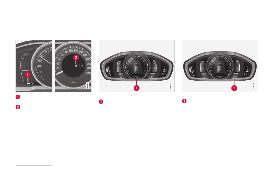
Outside temperature gauge

The display for the outside temperature gauge
appears in the combined instrument panel.

Display for outside temperature gauge, digi-
tal instrument panel
Display for outside temperature gauge, ana-
logue instrument panel

When the temperature lies between +2 °C to -5
°C a snowflake symbol illuminates in the display.
This warns of icy roads. If the car has been sta-
tionary, the gauge may display a reading that is
too high.

Related information

Combined instrument panel (p. 66)

Trip meter

The trip meter display appears in the combined
instrument panel.

Trip meter, digital instrument.

Display for trip meter

12

The two trip meters 

T1

 and 

T2

 are used for

measuring short distances. The distance is
shown in the display.

Turn the left stalk switch thumbwheel to show
the required meter.

A long press (until the change occurs) on the
left-hand stalk switch's RESET button resets the
trip meter shown. For more information, see Trip
computer (p. 114).

Related information

Combined instrument panel (p. 66)

Clock

The clock display appears in the combined
instrument panel.

Clock, digital instrument panel.

Display for showing the time

13

Set the clock

The clock can be adjusted in the menu system
MY CAR, see MY CAR (p. 113).

Related information

Combined instrument panel (p. 66)

12

Display appearance may differ depending on instrument variant.

INSTRUMENTS AND CONTROLS

76

Combined instrument panel -

license agreement

A license is an agreement for the right to oper-
ate a certain activity or the right to use someone
else's entitlement according to the terms and
conditions in the agreement. The following text is
Volvo's agreement with the manufacturer/devel-
oper.

Combined Instrument Panel Software

Open Source Software Notice

This product uses certain free / open source and
other software originating from third parties, that
is subject to the GNU Lesser General Public
License version 2 (LGPLv2), The FreeType
Project License ("FreeType License") and other
different and/or additional copy right licenses,
disclaimers and notices. The links to access the
exact terms of LGPLv2, and the other open
source software licenses, disclaimers,
acknowledgements and notices are provided to
you below. Please refer to the exact terms of the
relevant License, regarding your rights under said
licenses. Volvo Car Corporation (VCC) offers to
provide the source code of said free/open source
software to you for a charge covering the cost of
performing such distribution, such as the cost of
media, shipping and handling, upon written
request. Please contact your nearest Volvo
Dealer.

The offer is valid for a period of at least three (3)
years from the date of the distribution of this
product by VCC / or for as long as VCC offers
spare parts or customer support.

Portions of this product uses software
copyrighted 

© 2007 The FreeType Project

(www.freetype.org). All rights reserved.

Portions of this product uses software with
Copyright 

© 1994–2013 Lua.org, PUC-Rio

(http://www.lua.org/)

This product includes software under
following licenses:

LGPL v2.1: http://www.gnu.org/licenses/old-
licenses/lgpl-2.1.html

GNU FriBidi

DevIL

The FreeType Project License: http://
git.savannah.gnu.org/cgit/freetype/freetype2.git/
tree/docs/FTL.TXT

FreeType 2

MIT License: http://opensource.org/licenses/
mit-license.html

Lua

13

The time is shown in the middle of the instrument panel when an analogue instrument panel is fitted.

INSTRUMENTS AND CONTROLS

}}

* Option/accessory.

77

Symbols in the display

There are a variety of different symbols in the
display in the car. The symbols are divided into
warning, indicator and information symbols.

Shown below are the most common symbols with
their meanings and a reference to where in the
manual further information can be found.

 - Red warning symbol, illuminates when a

fault has been indicated which could affect the
safety and/or driveability of the car. An explana-
tory text is shown on the information display in
the combined instrument panel at the same time.

 - When one of the car's systems does not

behave as intended, this information symbol illu-
minates, and a text appears on the information
display in the combined instrument panel. The
yellow information symbol can also illuminate in
conjunction with other symbols.

Warning symbols in the combined
instrument panel

Symbol

Specification

See

Low oil pressure

(p. 73)

Parking brake
applied, digital
instrument panel

(p. 73),
(p. 293)

Symbol

Specification

See

Parking brake
applied, analogue
instrument panel

(p. 73)

Airbags – SRS

(p. 32),
(p. 73)

Seatbelt reminder

(p. 28),
(p. 73)

Alternator not charg-
ing

(p. 73)

Fault in brake sys-
tem

(p. 73),
(p. 291)

Warning, safety
mode

(p. 32),
(p. 42),
(p. 73)

Control symbols in the combined
instrument panel

Symbol

Specification

See

ABL fault

*

(p. 71),
(p. 94)

Emissions system

(p. 71)

ABS fault

(p. 71),
(p. 291)

Symbol

Specification

See

Rear fog lamp on

(p. 71),
(p. 98)

Stability system,
ESC (Electronic
Stability Control),
Trailer stability
assist

*

(p. 71),
(p. 189),
(p. 310)

Stability system,
sport mode

(p. 71),
(p. 189)

Engine preheater
(diesel)

(p. 71)

Low level in fuel
tank

(p. 71),
(p. 143)

Information, read
display text

(p. 71)

Main beam On

(p. 71),
(p. 91)

Left-hand direction
indicators

(p. 71)

Right-hand direc-
tion indicators

(p. 71)

Start/Stop

*, engine

auto-stopped

(p. 71),
(p. 279)

||

INSTRUMENTS AND CONTROLS

* Option/accessory.

78

Symbol

Specification

See

ECO function

* on

(p. 71),
(p. 287)

Tyre pressure sys-
tem

*

(p. 71), Tyre
monitoring
(TM)

*

(p. 328)

Information symbols in the combined
instrument panel

Symbol

Specification

See

Main beam with auto
dimming - AHB

*

(p. 92)

Camera sensor

*,

Laser sensor

*

(p. 92),
(p. 227),
(p. 236),
(p. 249),
(p. 254)

Adaptive cruise con-
trol

*

(p. 214)

Adaptive cruise con-
trol

*

(p. 206),
(p. 214)

Adaptive cruise con-
trol

*, Distance Warn-

ing

* (Distance Alert)

(p. 214),
(p. 199)

Adaptive cruise con-
trol

*

(p. 205)

Symbol

Specification

See

Cruise control

*

(p. 194)

Speed limiter

(p. 191)

Radar sensor

*

(p. 214),
(p. 202),
(p. 236)

Start/Stop

*

(p. 285)

Start/Stop

*

(p. 285)

Start/Stop

*

(p. 285)

Distance warning

*

(Distance Alert), City
Safety

TM

, Collision

warning system

*,

Auto-brake

*

(p. 202),
(p. 227),
(p. 236)

Engine block and
passenger compart-
ment heater

*

(p. 143)

Symbol

Specification

See

Engine block heater
and passenger com-
partment heater

*

Service required

(p. 143)

Activated timer

*

(p. 143)

Activated timer

*

(p. 143)

ABL system

*

(p. 94)

Low battery

(p. 143)

Park Assist Pilot -
PAP

*

(p. 263)

Rain sensor

*

(p. 102)

Lane assistance

*

(p. 252)

Driver Alert System

*,

Lane assistance

*

(p. 254)

INSTRUMENTS AND CONTROLS

}}

* Option/accessory.

79

Symbol

Specification

See

Driver Alert System

*,

Lane assistance

*

(p. 249),
(p. 254)

Driver Alert System

*,

Time for a break

(p. 248)

Driver Alert System

*,

Time for a break

(p. 249)

Gear shift indicator

(p. 274)

Gear positions

(p. 274)

Recorded speed
information

*

(p. 244)

Measuring the oil
level

(p. 345)

Information symbols in the roof console
display

Symbol

Specification

See

Seatbelt reminder

(p. 31)

Airbag, passenger seat,
activated

(p. 36)

Airbag, passenger seat,
deactivated

(p. 36)

Related information

Combined instrument panel - meaning of
indicator symbols (p. 71)

Combined instrument cluster - meaning of
warning symbols (p. 73)

Messages - handling (p. 113)

Volvo Sensus

Volvo Sensus is the heart of the personal Volvo
experience and connects you with the car and
outside world. Sensus provides information,
entertainment and assistance when it is needed.
Sensus consists of intuitive functions that both
enhance the car journey and simplifies owner-
ship of the car.

An intuitive navigation structure makes it possible
to receive relevant support, information and
entertainment when it is necessary, without dis-
tracting the driver.

Sensus covers all the car's solutions that enable
connection

* to the outside world and provides

you with intuitive control over all the car's capabil-
ities.

Volvo Sensus combines and presents many func-
tions in several of the car's systems on the centre
console's screen. With Volvo Sensus the car can
be personalised by means of an intuitive user

||

INSTRUMENTS AND CONTROLS

* Option/accessory.

80

interface. Settings can be made in Car settings,
Audio and media, Climate control, etc.

With the centre console buttons and controls or
the steering wheel's right-hand keypad

* functions

can be activated or deactivated and many differ-
ent settings can be made.

With a press on MY CAR all settings related to
the driving and control of the car are presented,
such as City Safety, locks and alarm, automatic
fan speed, setting the clock, etc.

With a press on the respective function RADIO,
MEDIA, TEL

*, 

*, NAV* and CAM

14

 other

sources, systems and functions can be activated,
e.g. AM, FM, CD, DVD

*, TV*, Bluetooth

®

*, naviga-

tion

* and park assist camera*.

For more information about all functions/
systems, see the relevant section in the owner's
manual or its supplement.

Overview

Control panel in centre console. The figure is schematic

- the number of functions and layout of the buttons both

vary, depending on the equipment selected and the mar-

ket.

Navigation

* - NAV, see separate supplement

(Sensus Navigation).
Audio and media - RADIO, MEDIA, TEL

*, see

separate supplement (Sensus Infotainment).

Internet-connected car - 

*, see separate

supplement (Sensus Infotainment).
Climate control system (p. 126).

Function settings - MY CAR, see MY CAR
(p. 113).

Key positions

The remote control key can be used to set the
vehicle's electrical system in different modes/
levels so that different functions are available;
see Key positions - functions at different levels
(p. 81).

Ignition switch with remote control key extracted/

inserted.

NOTE

For cars with the keyless start and lock sys-
tem

* function the key does not need to be

inserted into the ignition switch but can be
stored in e.g. a pocket. For more information
on the keyless start and lock system, see
Keyless drive

* (p. 169).

14

Applies to certain car models.

INSTRUMENTS AND CONTROLS

}}

81

Insert the key

1. Hold the end of the remote control key with

the detachable key blade and insert the key
in the ignition switch.

2. Then press the key in the lock up to its end

position.

IMPORTANT

Foreign objects in the ignition switch can
impair the function or destroy the lock.

Do not press in the remote control key incor-
rectly turned - Hold the end with the detacha-
ble key blade; see Detachable key blade -
detaching/attaching (p. 167).

Withdraw the key

Grip the remote control key and pull it out from
the ignition switch.

Key positions - functions at different

levels

To enable the use of a limited number of func-
tions with the engine switched off, the car's elec-
trical system can be set in 3 different levels - 

0, I

and 

II - with the remote control key. This owner's

manual describes these levels throughout using
the denomination "key positions".

The following table shows the functions available
in each key position/level.

Level

Functions

0

Odometer, clock and temperature
gauge are illuminated.

Electrically operated seats can be
adjusted.

The audio system can be used for
a limited time - see the Sensus
Infotainment supplement.

I

Sunroof, power windows, 12 V
socket in the passenger compart-
ment, navigation, phone, ventilation
fan and windscreen wipers can be
used.

II

The headlamps come on.

Warning/indicator lamps illuminate
for 5 seconds.

Several other systems are acti-
vated. However, electric heating in
seat cushions and the rear window
can only be activated after starting
the engine.

This key position consumes a lot of
current from the starter battery and
should therefore be avoided!

||

INSTRUMENTS AND CONTROLS

* Option/accessory.

82

Selecting key position/level

Key position 0 - Unlock the car - This
means that the car's electrical system is at
level 0.

NOTE

To reach level I or II without starting the
engine - do not depress the brake/clutch
pedal when these key positions are due to be
selected.

Key position I - With the remote control key
fully inserted into the ignition switch

15

 -

Briefly press START/STOP ENGINE.

Key position II - With the remote control
key fully inserted into the ignition switch

15

 -

Give a long

16

 press on START/STOP

ENGINE.

Back to key position 0 - To return to key
position 0 from position II and I - Briefly
press on START/STOP ENGINE.

Audio system

For information on audio system functions with
remote control key removed, see the Sensus
Infotainment supplement.

Starting and stopping the engine

For information about starting/switching off the
engine, see Starting the engine (p. 270).

Towing

For important information about the remote con-
trol key during towing, see Towing (p. 311).

Related information

Key positions (p. 80)

Seats, front

The car's front seats have different setting
options for optimum seating comfort.

To adjust lumbar support

*, turn the wheel

17

.

Forward/backward: lift the handle to adjust
the distance to the steering wheel and ped-
als. Check that the seat is locked after
adjusting position.
To raise/lower the front edge of seat cush-
ion

*, pump up/down.

Adjust backrest rake, turn the wheel.

Raise/lower the seat

*, pump up/down.

Control panel for power seat

*, see Seats,

front - electrically operated (p. 84).

15

Not required for cars with keyless start and lock system

*.

16

Approx. 2 seconds.

17

Also applies to electrically operated seat.

INSTRUMENTS AND CONTROLS

* Option/accessory.

83

WARNING

Adjust the position of the driver's seat before

setting off, never while driving. Make sure that

the seat is in locked position in order to avoid

personal injury in the event of heavy braking

or an accident.

Adjusting the front seat head restraints

The height of the head restraints can be adjusted.

Adjust the head restraint based on the person's
height so that the whole of the back of the head
is covered if possible.

To adjust the height, the button (see illustration)
must be pressed while the restraint is moved up
or down.

The head restraint can be adjusted in three dif-
ferent positions.

Lowering the passenger seat backrest

*

The passenger seat backrest can be folded for-
ward to make room for long loads.

Move the seat as far back/down as possible.

Adjust the backrest to an upright position.

Lift the catches on the rear of the backrest
and fold it forward.

4. Push the seat forward so that the head

restraint "locks" in under the glovebox.

Raising takes place in reverse order.

WARNING

Do not use the seat behind the passenger

seat, or the rear centre seat, when the pas-

senger seat's backrest is lowered.

WARNING

Grasp the backrest and make sure that it is

properly locked after being folded up in order

to avoid personal injury in the event of sudden

braking or an accident.

Related information

Seats, front - electrically operated (p. 84)

Seats, rear (p. 85)

INSTRUMENTS AND CONTROLS

* Option/accessory.

84

Seats, front - electrically operated

The car's front seats have different setting
options for optimum seating comfort. The power
seat can be moved forward/backward and up/
down. The front edge of the seat cushion can be
raised/lowered. The backrest angle can be
changed.

Electrically operated seat

*

Front edge of seat cushion up/down

Raise/lower seat

Seat, forward/backward

Backrest rake

The power seats have overload protection which
is tripped if a seat is blocked by an object. If this
should happen, set the car's electrical system in

key position I or 0 and wait a short time before
adjusting the seat again.

Only one movement (forward/back/up/down)
can be made at a time.

Preparations

The seat can be adjusted for a certain time after
unlocking the door with the remote control key
without the key in the ignition switch. Seat adjust-
ment is normally made in key position I and can
always be made when the engine is running.

Seat with memory function

*

The memory function stores settings for the seat
and the door mirrors.

Store setting

Memory button

Memory button

Memory button

Button for storing settings

1. Adjust the seat and the door mirrors.

2. Press and hold button M while pressing but-

ton 1, 2 or 3 simultaneously. Hold the but-
tons depressed until the acoustic signal is
heard and the text is shown the combined
instrument panel.

The seat must be adjusted again before a new
memory can be set.

Using a stored setting

Press one of the memory buttons 1-3 until the
seat and the door mirrors stop. If the button is
released, the movement of the seat and door mir-
rors will be interrupted.

Key memory

* in remote control key

All remote control keys can be used by different
drivers to store the settings for the driver's seat
and door mirrors

18

, see Remote control key - per-

sonalisation

* (p. 161).

18

Only if the car is equipped with power seat with memory and retractable power door mirrors.

INSTRUMENTS AND CONTROLS

}}

* Option/accessory.

85

Emergency stop

If the seat accidentally begins to move, press one
of the setting buttons for the seat or memory
buttons in order to stop the seat.

WARNING

Risk of crushing! Make sure that children do

not play with the controls. Check that there

are no objects in front of, behind or under the

seat during adjustment. Make sure that none

of the passengers in the rear seat is in danger

of becoming trapped.

Heated seats

For heated seats, see Heated front seats

*

(p. 133) and Heated rear seat

* (p. 133).

Related information

Seats, front (p. 82)

Seats, rear (p. 85)

Seats, rear

The rear seat backrest and the outer seat head
restraints can be folded. The centre seat head
restraint can be adjusted to suit the height of the
passenger.

Head restraint, centre seat, rear

Adjust the head restraint according to passenger
height so that the whole of the back of the head
is covered if possible. Slide it up as required.

To lower the head restraint again, the button (see
illustration) must be pressed while the restraint is
carefully moved down.

The head restraint can be adjusted in five differ-
ent positions.

WARNING

The centre seat head restraint must be in its

lowest position when the centre seat is not

used. When the centre seat is used, the head

restraint must be correctly adjusted to the

height of the passenger so that it covers the

whole of the back of the head if possible.

Manual lowering of the outer head
restraints, rear seat

Pull the locking handle closest to the head
restraint to fold the head restraint forward.

The head restraint is moved back manually.

WARNING

The head restraint must be in locked position

after being folded up.

||

INSTRUMENTS AND CONTROLS

86

Lowering the rear seat backrest

IMPORTANT

When the backrest is to be folded, the rear
seat cup holder must not be open and there
must be no objects in the rear seat. Nor may
the seat belts be connected. Otherwise there
is a risk of damage to the rear seat uphols-
tery.

NOTE

The front seats may need to be pushed for-
wards, and/or the backrests adjusted
upwards, in order that the rear backrests can
be fully folded forward.

Both sections can be folded separately.

If the entire backrest is to be folded then the
different sections should be folded sepa-
rately.

If the right-hand section is being lowered -
release and adjust head restraint for the cen-
tre seat, see the earlier section "Head
restraint, centre seat, rear".

The outer head restraints are lowered auto-
matically when the backrests are lowered.
Pull up the backrest's locking handle 
while folding the backrest forward at the
same time. A red indicator on the lock catch

 shows that the backrest is no longer

locked in place.

NOTE

When the backrests have been lowered the
head restraints must be moved forward
slightly so as not to make contact with the
seat cushion.

Raising takes place in reverse order.

NOTE

When the backrest has been raised, the red
indicator should no longer be showing. If it is
still showing then the backrest is not locked
in place.

WARNING

Check that the backrests and head restraints

in the rear seat are locked properly after

being folded up.

Related information

Seats, front (p. 82)

Seats, front - electrically operated (p. 84)

INSTRUMENTS AND CONTROLS

}}

* Option/accessory.

87

Steering wheel

The steering wheel can be adjusted in different
positions and has controls for horn and cruise
control, as well as menu, audio and phone con-
trol.

Adjusting

Adjusting the steering wheel.

Lever - releasing the steering wheel

Possible steering wheel positions

The steering wheel can be adjusted for both
height and depth:

1. Push the lever forwards to release the steer-

ing wheel.

2. Adjust the steering wheel to the position that

suits you.

3. Pull the lever back to fix the steering wheel

in place. If the lever is stiff, press the steering
wheel lightly at the same time as you push
the lever back.

WARNING

Adjust the steering wheel and fix it before

driving away. The steering wheel must never

be adjusted while driving.

With speed related power steering

* the level of

steering force can be adjusted, see Adjustable
steering force

* (p. 186).

Keypads

* and paddles*

Keypads and paddles in the steering wheel.

Cruise control

* (p. 194)* and Adaptive cruise

control (ACC)

* (p. 203)*.

Paddle for manual gear changing in an auto-
matic gearbox, see Automatic gearbox -
Geartronic

* (p. 274).

Audio and phone control, see supplement,
Sensus Infotainment.

||

INSTRUMENTS AND CONTROLS

* Option/accessory.

88

Horn

Horn.

Press the centre of the steering wheel to signal.

Light switches

The headlamp control activates and adjusts the
external lighting. It is also used to adjust display
and instrument lighting and ambience lights
(p. 100).

Overview, light switches.

Thumbwheel for adjusting display and instru-
ment lighting as well as ambience lights

*

Button for rear fog lamp

Knob for lighting while driving and parking

Thumbwheel for headlamp levelling

A car with LED

19

 headlamps

* has automatic

headlamp levelling and therefore does not have
the thumbwheel for headlamp levelling.

Knob positions

Position

Specification

Daytime running lights

A

 when the

car's electrical system is in key
position II or the engine is running.

Main beam flash can be used.

Daytime running lights, side marker
lamps rear and position lamps
when the car's electrical system is
in key position II or the engine is
running.

Side marker lamps rear and posi-
tion lamps when the car is parked

B

.

Main beam flash can be used.

Daytime running lights, side marker
lamps rear and position lamps in
daylight when the car's electrical
system is in key position II or the
engine is running.

Dipped beam, side marker lamps
rear and position lamps in weak
daylight or darkness, or when rear
fog lamps are activated.

The tunnel detection (p. 91)

*

function is activated.

19

LED (Light Emitting Diode)

INSTRUMENTS AND CONTROLS

* Option/accessory.

89

Position

Specification

The Active main beam (p. 92)

*

function can be used.

Main beam can be activated when
dipped beam is switched on.

Main beam flash can be used.

Dipped beam, side marker lamps
rear and position lamps.

Main beam can be activated.

Main beam flash can be used.

A

Fitted in or under the front bumper.

B

Also at idle when the engine is running, provided that the knob

is moved to this position from another position.

Volvo recommends that 

 mode is used

when the car is driven.

WARNING

The car's audio system is not able to deter-

mine when daylight is too weak or sufficiently

strong, e.g. in fog and rain, in all situations.
The driver is always responsible for ensuring

that the car is driven with a beam pattern suit-

able for the traffic situation and in accordance

with applicable traffic regulations.

Display and instrument lighting

Different display and instrument lighting is
switched on depending on key position; see Key
positions - functions at different levels (p. 81).

The display lighting is automatically subdued in
darkness - the sensitivity is set with the thumb-
wheel.

The intensity of the instrument lighting is
adjusted with the thumbwheel.

Headlamp levelling

The load in the car changes the vertical align-
ment of the headlamp beam, which could dazzle
oncoming motorists. Avoid this by adjusting the
height of the beam. Lower the beam if the car is
heavily laden.

1. Leave the engine running, or have the car's

electrical system in key position I.

2. Roll the thumbwheel up/down to raise/lower

beam alignment.

Thumbwheel positions for different load cases.

Only driver

Driver and passenger in the front passenger
seat
Occupants in all seats

Occupants in all seats and maximum load in
the cargo area
Driver and maximum load in the cargo area

Related information

Position lamps (p. 90)

Daytime running lights (p. 90)

Main/dipped beam (p. 91)

INSTRUMENTS AND CONTROLS

90

Position lamps

Position lamps are switched on using the head-
lamp control's knob.

Knob for headlamp control in the position for position

lamps.

Turn the knob to the position for 

 (number

plate lighting is switched on at the same time).

If the car's electrical system is in key position II or
the engine is running then the daytime running
lights also switch on.

When it is dark outside and the tailgate is
opened the rear position lamps illuminate to alert
traffic behind. This takes place irrespective of
what position the knob is in or what key position
the car's electrical system is in.

When driving for more than 30 seconds at max.
10 km/h (approx. 6 mph), or if the speed
exceeds 10 km/h (approx. 6 mph), the daytime

running lights are switched on and 

Reset light

switch position

 is shown in the combined

instrument panel, which prompts you to turn to a
mode other than 

.

Related information

Light switches (p. 88)

Daytime running lights

With the knob for headlamp control in 
position, and the car's electrical system in key
position 

II or the engine running, the daytime

running lights are activated automatically in day-
light.

Daytime running lights during the day.
DRL

Knob for headlamp control in AUTO position.

With the knob for headlamp control in 
position the daytime running lights (Daytime
Running Lights - DRL) are activated automati-
cally when the car is driven in daylight. A light
sensor on the top of the instrument panel
changes from daytime running lights to dipped
beam at twilight or when daylight becomes too
weak. Switching to dipped beam also takes place
when the rear fog lamps are activated.


Content   ..  2  3  4  5   ..