Volkswagen Golf / Golf GTI / Golf Variant. Manual - part 965


  Index      Volkswagen     Volkswagen Golf / Golf GTI / Golf Variant - service repair manual 2013 year


Search            copyright infringement  


Content   ..  963  964  965  966   ..


Volkswagen Golf / Golf GTI / Golf Variant. Manual - part 965


❑ Removing and installing. Refer to 

⇒ “2.29  Sunroof Button E325 , Removing and Installing”, page 274

 .

2.7

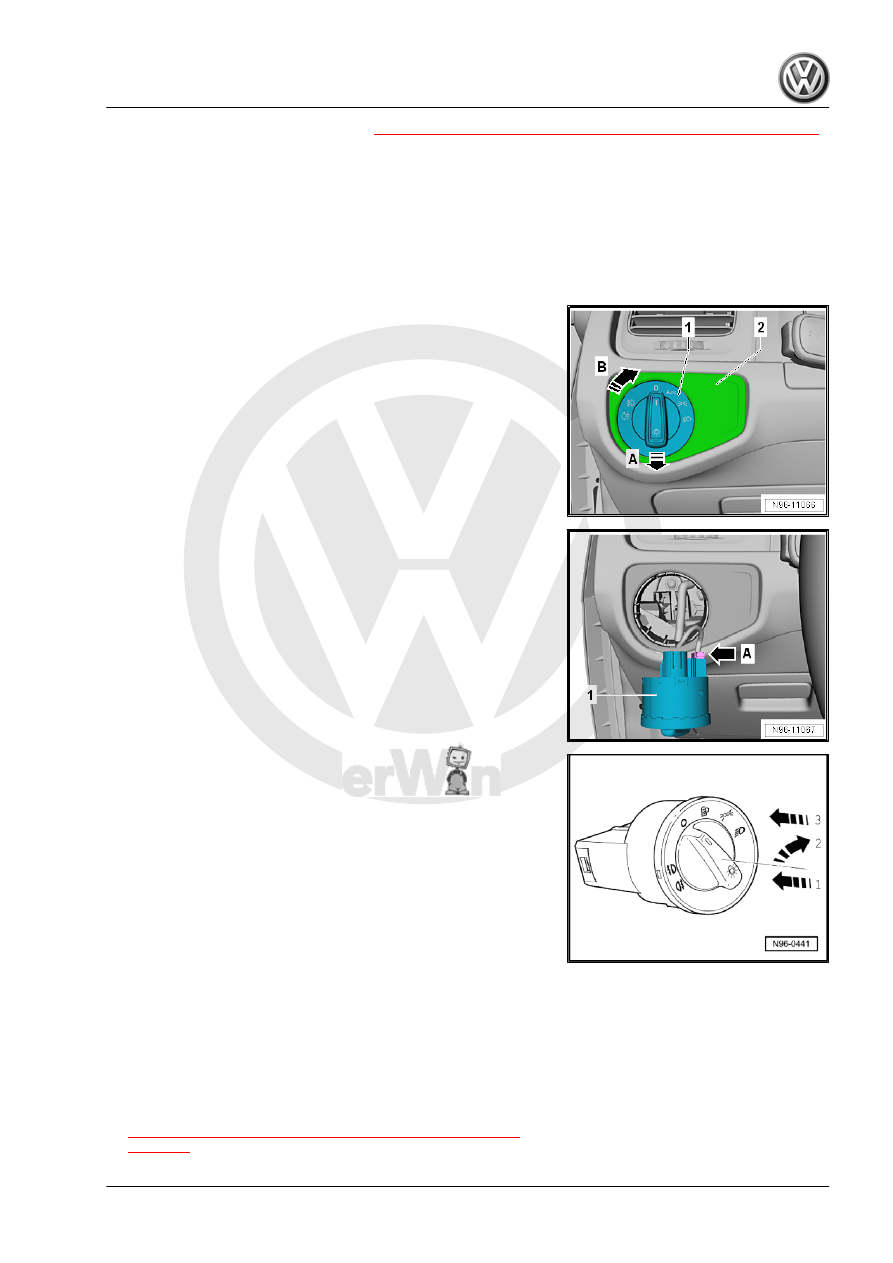
Rotary Light Switch - EX1- , Removing

and Installing

Removing
– Turn off the ignition and all electrical equipment.
– Remove the ignition key, if equipped.
– Push in the Rotary Light Switch - EX1- rotary handle -1- op‐

posite the direction of the -arrow A- and turn in the direction of

the -arrow B-.

– Hold the rotary handle -1- in this position.
– Remove the entire Rotary Light Switch - EX1- in the direction

of the -arrow A- from the instrument panel.

– Disconnect the connectors -arrow A-.

– Remove the Rotary Light Switch - EX1- -1-.
Installing
Install in the reverse order of removal while paying attention to

the following:

– Tighten the Rotary Light Switch - EX1- and push in the light

switch rotary handle in direction of -arrow 1- and at the same

time turn right in direction of - arrow 2-.

– Hold the rotary handle in this position and install the Rotary

Light Switch - EX1- in the instrument panel -3-.

– Turn the rotary handle to “0” to lock the switch in the instrument

panel.

– Perform a function test.

2.8

Headlamp Range Control Adjuster -

E102- , Removing and Installing

Removing
– Turn off the ignition and all electrical equipment.
– Remove the ignition key, if equipped.
– Remove the Rotary Light Switch - EX1- . Refer to

⇒ “2.7  Rotary Light Switch EX1 , Removing and Installing”,

page 265

 .

– Remove the bolt -1-.
– Remove the trim -2- using the Headlamp Range Control Ad‐

juster - E102- from the instrument panel.

– Release and disconnect the connectors.

– Push the catches on the Headlamp Range Control Adjuster -

E102- -1- in the direction of the -arrow A-.

– Push the Headlamp Range Control Adjuster - E102- -1-.
Installing
Install in reverse order of removal.
– Perform a function test.

2.9

Driving Profile Selection Button - E735- ,

Removing and Installing

Removing and installing. Refer to

⇒ “2.14 Center Console Switch Module 1 and 2 EX23 / EX30 ,

Removing and Installing”, page 267

 .

2.10

Start/Stop Mode Button - E693- , Re‐

moving and Installing

Removing and installing. Refer to

⇒ “2.14 Center Console Switch Module 1 and 2 EX23 / EX30 ,

Removing and Installing”, page 267

 .

2.11

ASR/ESP Button - E256- , Removing

and Installing

Removing and installing. Refer to

⇒ “2.14 Center Console Switch Module 1 and 2 EX23 / EX30 ,

Removing and Installing”, page 267

 .

2.12

Parking Aid Button - E266- , Removing

and Installing

Removing and installing. Refer to

⇒ “2.14 Center Console Switch Module 1 and 2 EX23 / EX30 ,

Removing and Installing”, page 267

 .

2.13

Parallel Parking Assistance Button -

E581- , Removing and Installing

Removing and installing. Refer to

⇒ “2.14 Center Console Switch Module 1 and 2 EX23 / EX30 ,

Removing and Installing”, page 267

 .

2.14

Center Console Switch Module 1 and 2

-EX23- / -EX30- , Removing and Instal‐

ling

Special tools and workshop equipment required
♦ Trim Removal Wedge - 3409-
The following buttons are installed on the left and right sides of

the selector lever, depending on the vehicle equipment, in two

button modules. The same procedure is used to remove and in‐

stall the following components. The procedure is only described

for one button module. A removed button module cannot be dis‐

assembled.
Center Console Switch Module 1 - EX23-
♦ Driving Profile Selection Button - E735-
♦ Start/Stop Mode Button - E693-
♦ ASR/ESP Button - E256-
Center Console Switch Module 2 - EX30-
♦ Parking Aid Button - E266-
♦ Parallel Parking Assistance Button - E581-

Caution

Risk of damaging the component surfaces.

♦ When positioning a prying tool, put commercially available

adhesive tape over the component in the visible area.

Removing
– Turn off the ignition and all electrical equipment.
– Remove the ignition key, if equipped.
– Remove the selector lever boot. Refer to ⇒  Rep. Gr.  34 ;

Selector Mechanism; Selector Lever Handle, Removing and

Installing .

– Pry the trim -1- up using the -3409- .

– Lift the driver side button module -1- or the front passenger

side button module -2- upward from the center console.

– Release and disconnect the connector -1-.

– Remove the button module -2-.
Installing
Install in reverse order of removal.
– Perform a function test.

2.15

Emergency Flasher Switch - EX3- , Re‐

moving and Installing

Removing
– Turn off the ignition and all electrical equipment.
– Remove the ignition key, if equipped.
– Grasp the Front Passenger Airbag -Disabled- Indicator Lamp

- K145- -1- at the side -A arrows- and remove from the instru‐

ment panel.

– Release and disconnect the connectors.
– Loosen the catches -1-.

– Push the Emergency Flasher Switch - EX3- -2- out of the Front

Passenger Airbag -Disabled- Indicator Lamp - K145- in the

direction of the -arrow A-.

Installing
Install in reverse order of removal.
– Perform a function test.


Content   ..  963  964  965  966   ..