Volkswagen Golf / Golf GTI / Golf Variant. Manual - part 951


  Index      Volkswagen     Volkswagen Golf / Golf GTI / Golf Variant - service repair manual 2013 year


Search            copyright infringement  


Content   ..  949  950  951  952   ..


Volkswagen Golf / Golf GTI / Golf Variant. Manual - part 951


11

Automatic Headlamp Range Control

⇒ “11.1 Overview - Automatic Headlamp Range Control”,

page 209
⇒ “11.1.2 Overview - Automatic Headlamp Range Control, Wag‐

on”, page 210
⇒ “11.2 Control Module for Headlamp Range/Cornering Lamp

and Headlamp Range, Removing and Installing”, page 211

11.1

Overview - Automatic Headlamp Range

Control

⇒ “11.1.1 Overview - Automatic Headlamp Range Control, Se‐

dan”, page 209
⇒ “11.1.2 Overview - Automatic Headlamp Range Control, Wag‐

on”, page 210

11.1.1

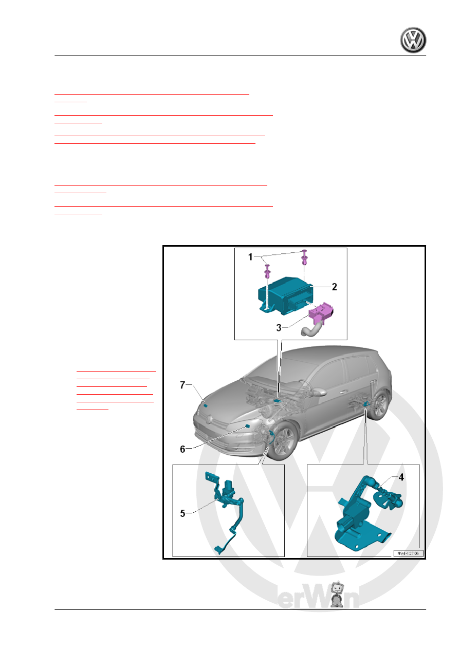
Overview - Automatic Headlamp Range Control, Sedan

1 - Expanding Clip

❑ Quantity: 2

2 - Control Module

❑ Without cornering

lamps: Headlamp

Range Control Module -

J431-

❑ With cornering lamps:

Cornering Lamp and

Headlamp Range Con‐

trol Module - J745-

❑ Removing and instal‐

ling. Refer to

⇒ “11.2 Control Module

for Headlamp Range/

Cornering Lamp and

Headlamp Range, Re‐

moving and Installing”,

page 211

 .

3 - Connector
4 - Left Rear Level Control Sys‐

tem Sensor - G76-

❑ On the rear control arm
❑ Overview. Refer to ⇒ 

Suspension, Wheels,

Steering; Rep. Gr.  43 ;

Level Control System

Sensor; Overview -

Rear Level Control Sys‐

tem Sensor .

5 - Left Front Level Control

System Sensor - G78-

❑ On the control arm in the

front

❑ For HID headlamp with

cornering lamp

❑ Overview. Refer to ⇒  Suspension, Wheels, Steering; Rep. Gr.  43 ; Level Control System Sensor; Over‐

view - Front Level Control System Sensor .

6 - Left Headlamp Beam Adjustment Motor - V48-

❑ Removing and installing. Refer to

⇒ “1.8 Left/Right Headlamp Beam Adjustment Motor V48 / V49 , Removing and Installing”, page 111

 .

7 - Right Headlamp Beam Adjustment Motor - V49-

❑ Removing and installing. Refer to

⇒ “1.8 Left/Right Headlamp Beam Adjustment Motor V48 / V49 , Removing and Installing”, page 111

 .

11.1.2

Overview - Automatic Headlamp Range Control, Wagon

1 - Expanding Clip

❑ Quantity: 2

2 - Control Module

❑ Without cornering

lamps: Headlamp

Range Control Module -

J431-

❑ With cornering lamps:

Cornering Lamp and

Headlamp Range Con‐

trol Module - J745-

❑ Removing and instal‐

ling. Refer to

⇒ “11.2 Control Module

for Headlamp Range/

Cornering Lamp and

Headlamp Range, Re‐

moving and Installing”,

page 211

 .

3 - Connector
4 - Left Rear Level Control Sys‐

tem Sensor - G76-

❑ On the rear control arm
❑ Overview. Refer to ⇒ 

Suspension, Wheels,

Steering; Rep. Gr.  43 ;

Level Control System

Sensor; Overview -

Rear Level Control Sys‐

tem Sensor .

5 - Left Front Level Control

System Sensor - G78-

❑ On the control arm in the

front

❑ For HID headlamp with

cornering lamp

❑ Overview. Refer to ⇒  Suspension, Wheels, Steering; Rep. Gr.  43 ; Level Control System Sensor; Over‐

view - Front Level Control System Sensor .

6 - Left Headlamp Beam Adjustment Motor - V48-

❑ Removing and installing. Refer to

⇒ “1.8 Left/Right Headlamp Beam Adjustment Motor V48 / V49 , Removing and Installing”, page 111

 .

7 - Right Headlamp Beam Adjustment Motor - V49-

❑ Removing and installing. Refer to

⇒ “1.8 Left/Right Headlamp Beam Adjustment Motor V48 / V49 , Removing and Installing”, page 111

 .

11.2

Control Module for Headlamp Range/

Cornering Lamp and Headlamp Range,

Removing and Installing

If the control module is being replaced, use the Vehicle Diagnostic

Tester and select the “Replacing” function for the respective con‐

trol module in “Guided Fault Finding”.
Removing
– Turn off the ignition and all electrical equipment.
– Remove the ignition key, if equipped.
– Remove the driver side instrument panel cover. Refer to ⇒ 

Body Interior; Rep. Gr.  68 ; Storage Compartments and Cov‐

ers; Driver Side Instrument Panel Cover, Removing and In‐

stalling .

– If installed, remove the driver side knee airbag. Refer to ⇒ 

Body Interior; Rep. Gr.  69 ; Knee Airbags; Overview - Knee

Airbag .

– Release and remove the expanding clip -3-.
– Remove the control module -1- rearward.
– Release and disconnect the connector -2-.

– To do this push the tab -1-, pivot the retaining bracket in the

direction of -arrow- and remove the connector.

Installing
Install in the reverse order of removal while paying attention to

the following:

– Push the expanding clip -2- in the opening -3- on the control

module -1-.

– Lock the expanding clip by turning 90° in direction of -arrow-.


Content   ..  949  950  951  952   ..